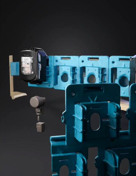
Blue Electrical Module 3D Model
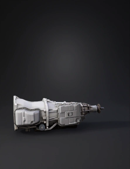
Car Transmission 3D Model
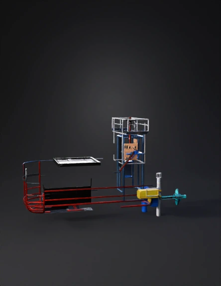
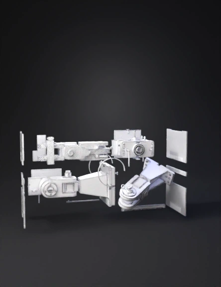
Exploded Mechanical Assembly 3D Model
Mechanical Assembly 3D Model
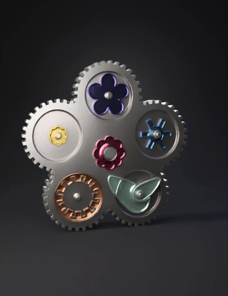
Intricate Gear Mechanism 3D Model
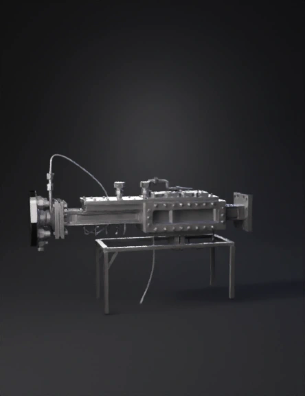
Industrial Machinery 3D Model
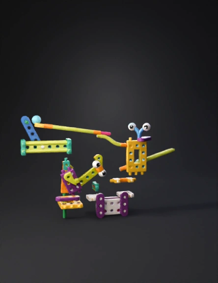
Colorful Construction Toy 3D Model
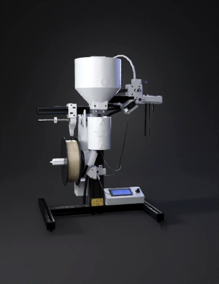
3d Printer Extruder 3D Model
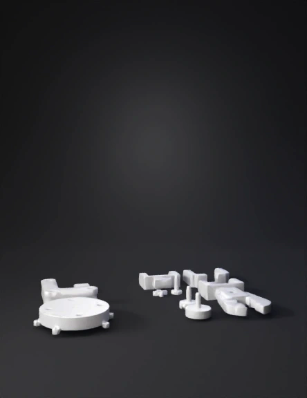
3d Printed Mechanical Parts 3D Model
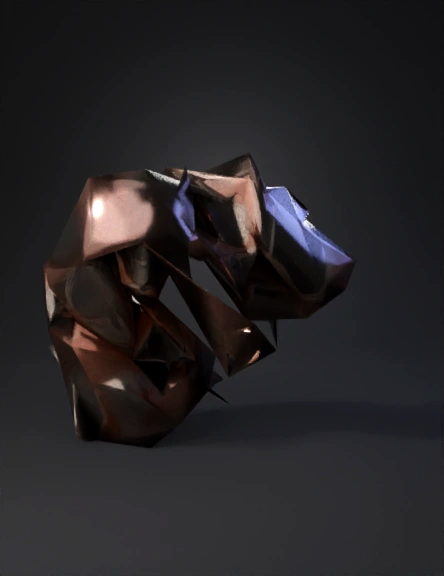
Engine Component 3D Model
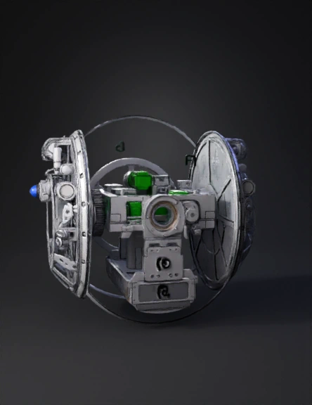
Optical Instrument 3D Model
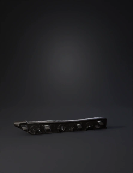
Plastic Bracket 3D Model
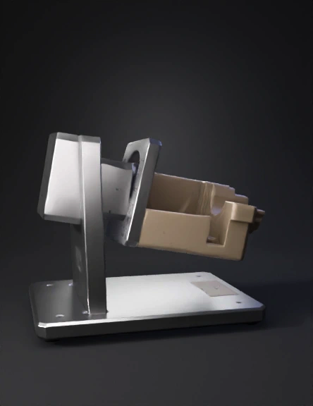
Mechanical Gripper 3D Model
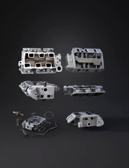
Engine Intake Manifold 3D Model
Mechanical Part 3D Model
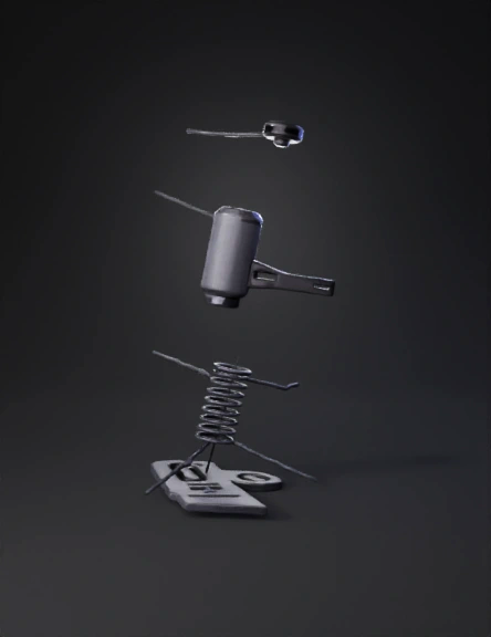
Spring Damper 3D Model
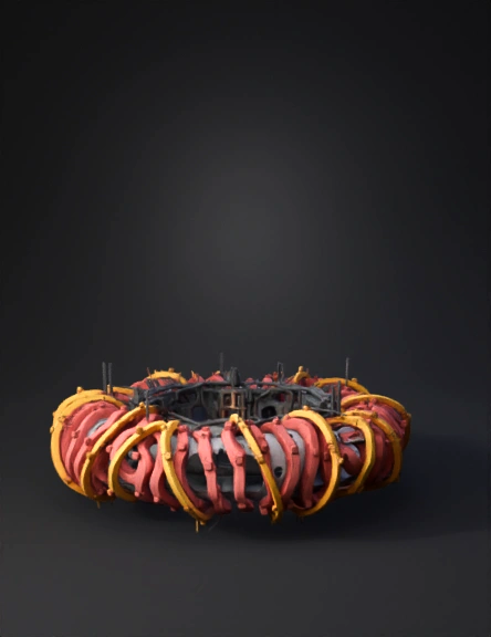
Torus Assembly 3D Model
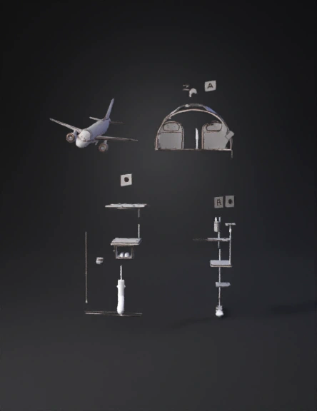
Airplane 3D Model