
Small Device Base 3D Model
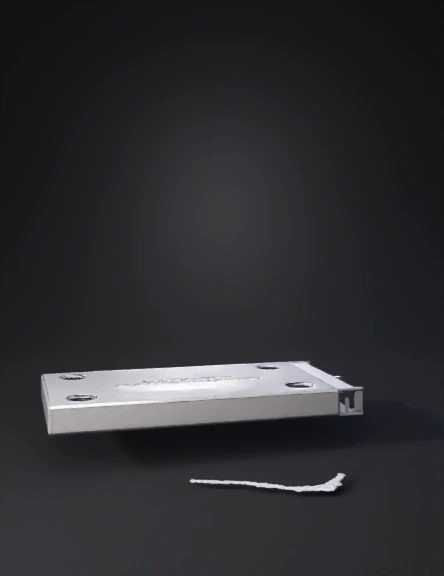
Rectangular Base Plate 3D Model
Plastic Base Plate 3D Model

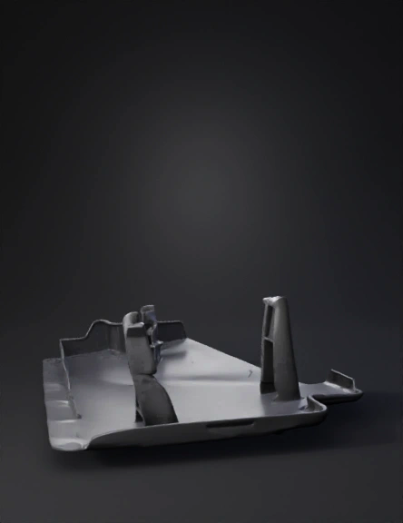
Irregular Plate 3D Model
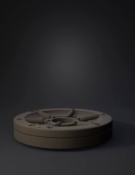
Circular Base Plate 3D Model
Machine Panel 3D Model
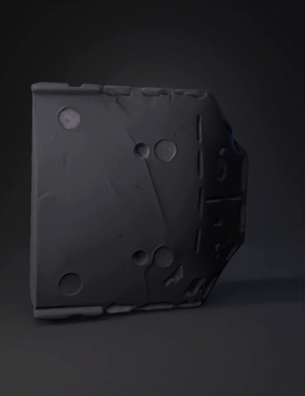
Metal Base Plate 3D Model
基座板三维模型 3D Model

Futuristic Base Platform 3D Model
Placa Base 3d 3D Model
Industrial Base 3D Model
Base Plate 3D Model
Plastic Base Plate 3D Model
Base Plate 3D Model
Machined Base Plate 3D Model
Base Plate 3D Model
Base Plate 3D Model
Base Plate 3D Model