?
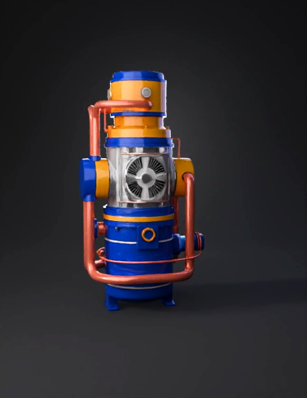
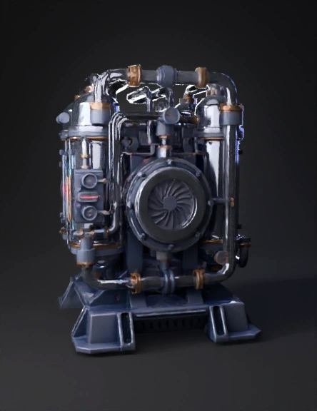
Compressors 3D Models
Find the best Compressors 3D Models, free download in STL, FBX, GLB, OBJ, 3MF, USDZ for 3D modeling and creation in Blender, 3D printing, game developing, animation, eCommerce, AR/VR and etc. Generated by Tripo AI 3D Generator.
You May Also Like :
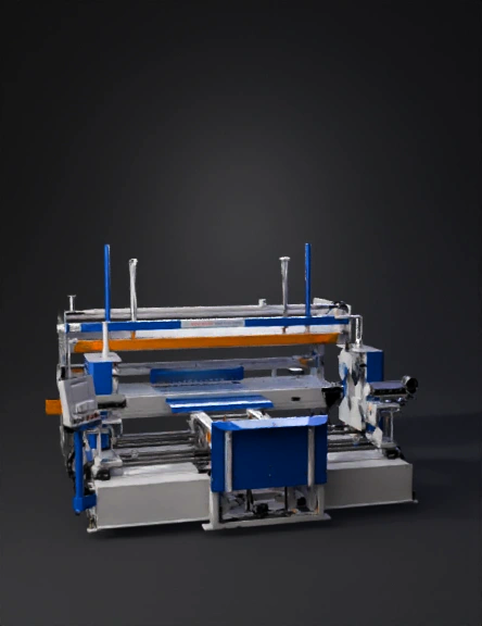
Industrial Machine 3D Model
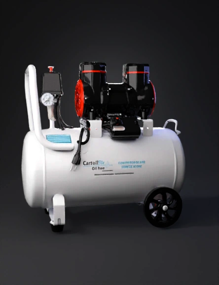
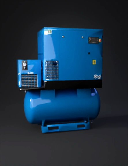
Air Compressor 3D Model
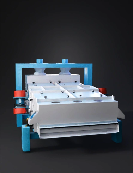
Filter Press 3D Model
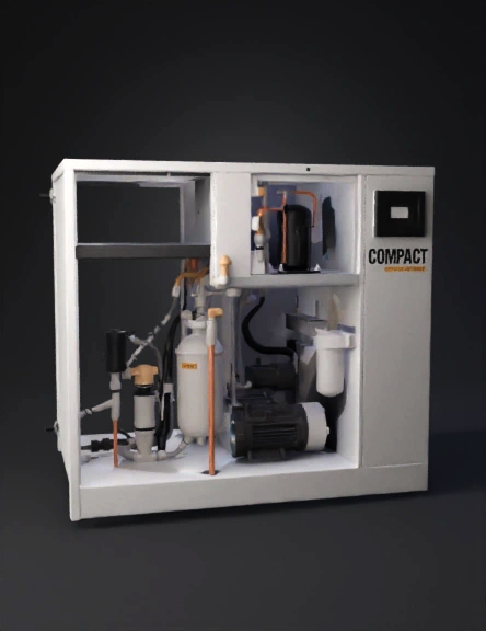
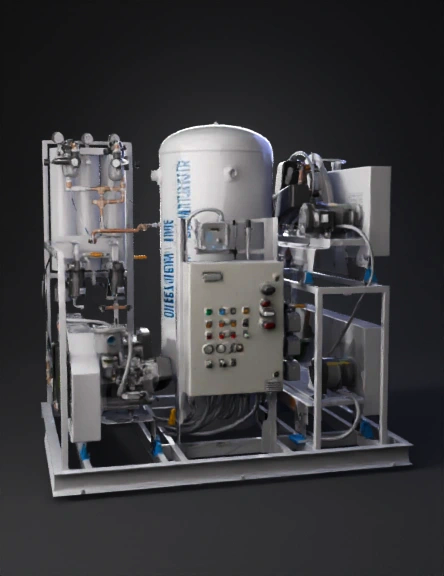
Industrial Air Compressor 3D Model
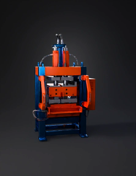
Industrial Hydraulic Press 3D Model
Industrial Air Compressor 3D Model
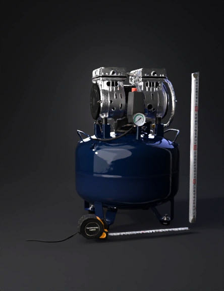
Medical Compressor 3D Model
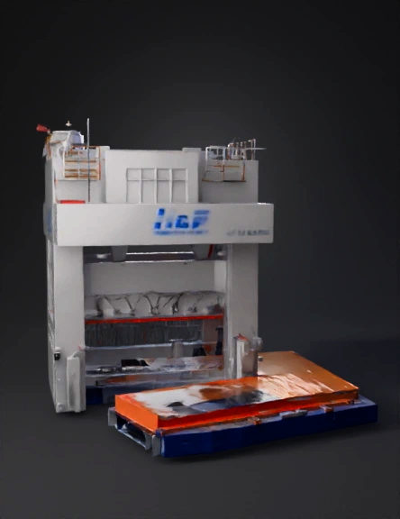
Industrial Press 3D Model
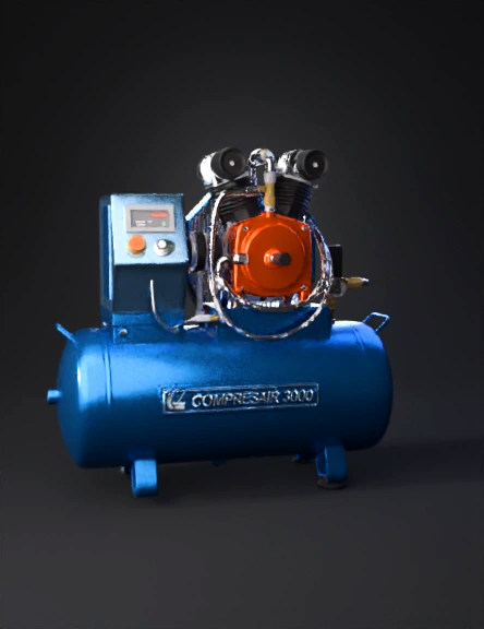
Air Compressor 3D Model
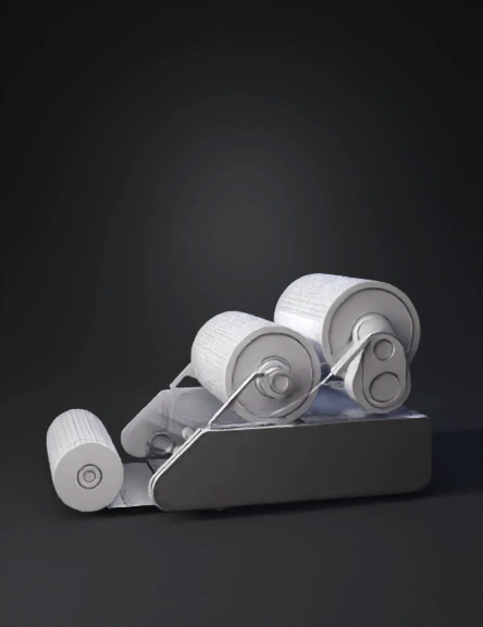
Double Roller Press 3D Model
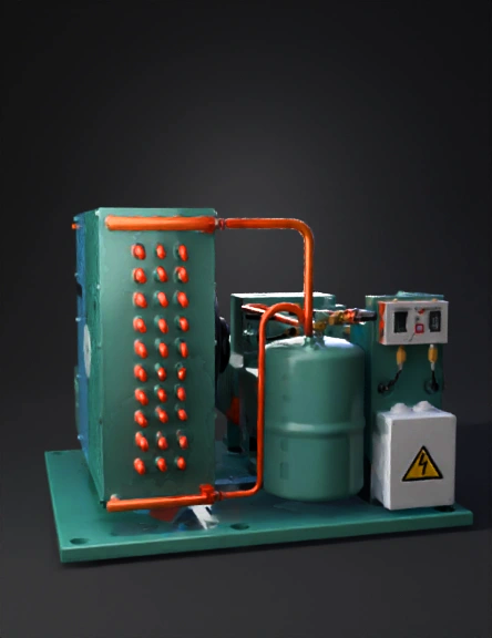
Industrial Refrigeration Compressor 3D Model
Turbine System 3D Model
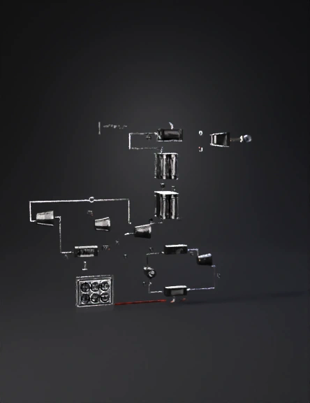
Compressor 3D Model
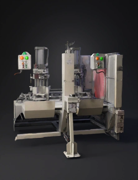
Industrial Machine 3D Model
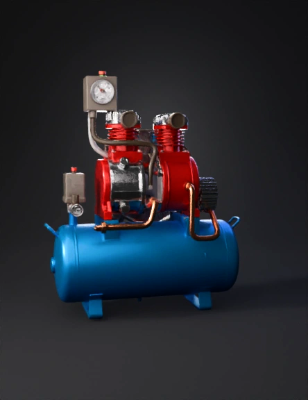
Air Compressor 3D Model
Воздушный Компрессор 3d Модель 3D Model
气体压缩机3d模型 3D Model
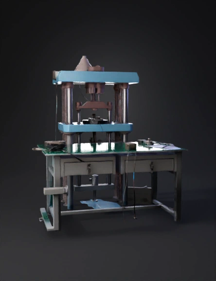
Compression Testing Machine 3D Model