?
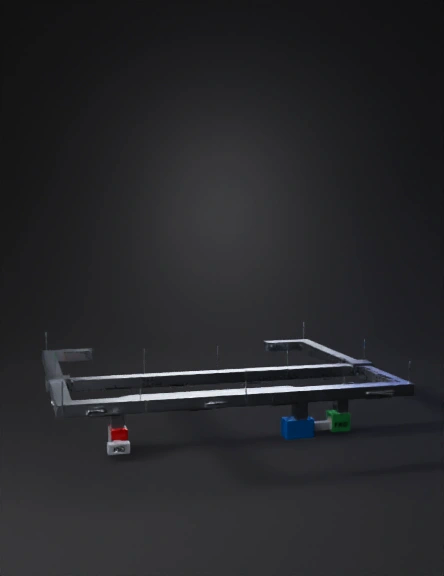
Ducting 3D Models
Find the best Ducting 3D Models, free download in STL, FBX, GLB, OBJ, 3MF, USDZ for 3D modeling and creation in Blender, 3D printing, game developing, animation, eCommerce, AR/VR and etc. Generated by Tripo AI 3D Generator.
You May Also Like :

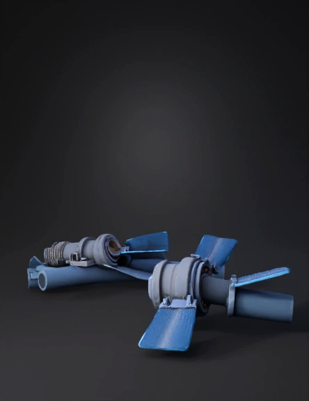
Industrial Ducting 3D Model
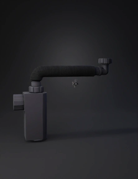
Gooseneck Hose 3D Model
管道组件3d模型 3D Model

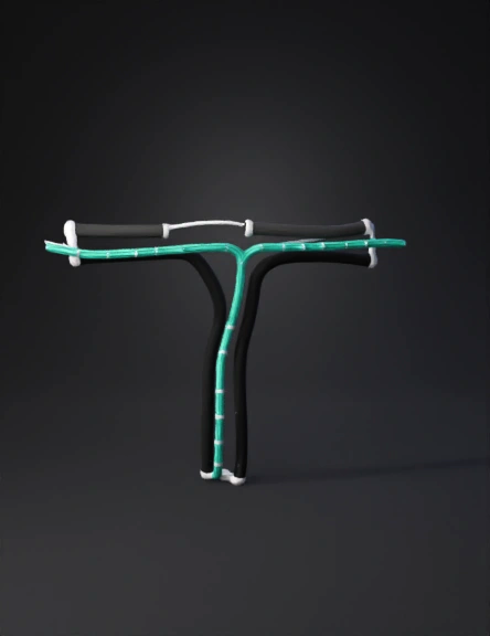
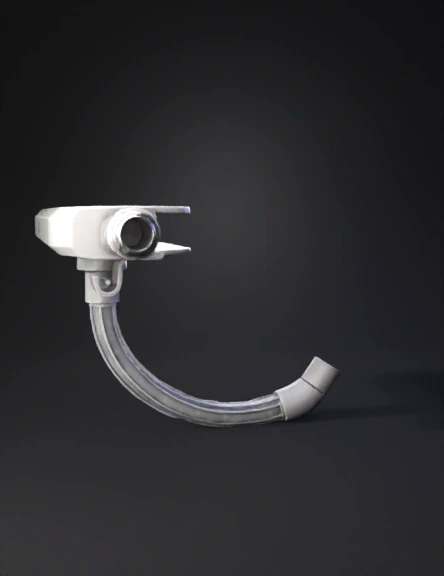
Air Intake Elbow 3D Model
防淤积管件3d模型 3D Model
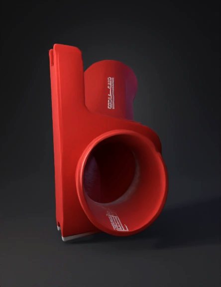
Red Funnel 3D Model
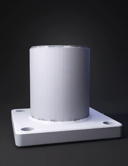
Duct Flange 3D Model
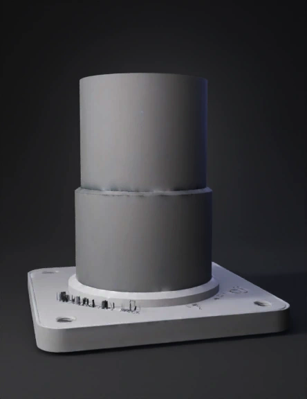
Circular Duct Flange 3D Model
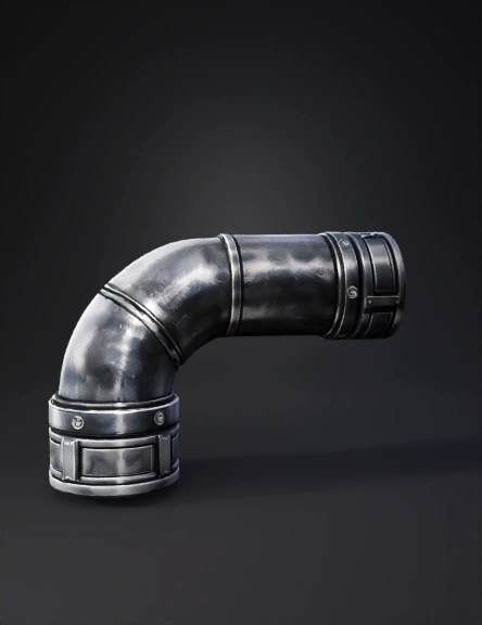
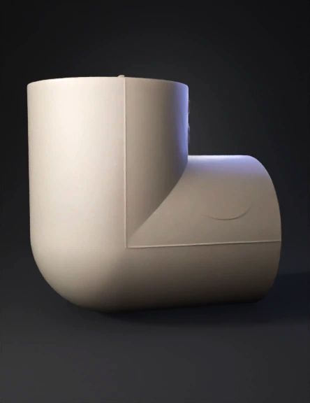
Industrial Pipe Elbow 3D Model
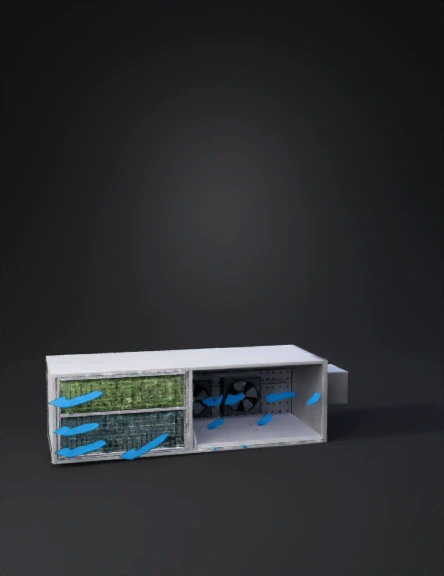
Industrial Air Handling Unit 3D Model

Aluminum Flexible Duct 3D Model
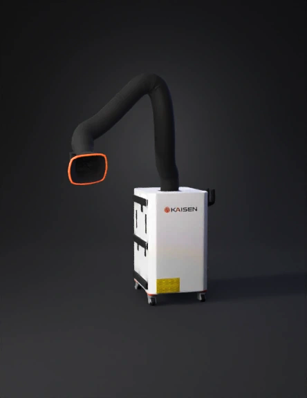
Industrial Fume Extractor 3D Model
水管弯头3d模型 3D Model
نموذج ثلاثي الأبعاد لمواسير 3D Model
Well Casing 3D Model
Ducting System 3D Model

Duct Elbow 3D Model
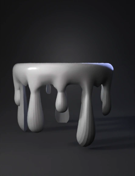
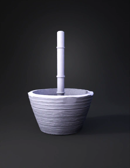
Dripping Ring 3D Model