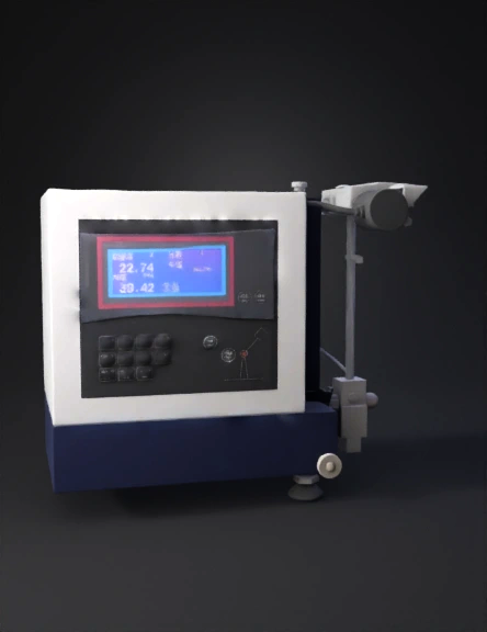
Measurement Instrument 3D Model

Steampunk Compass 3D Model
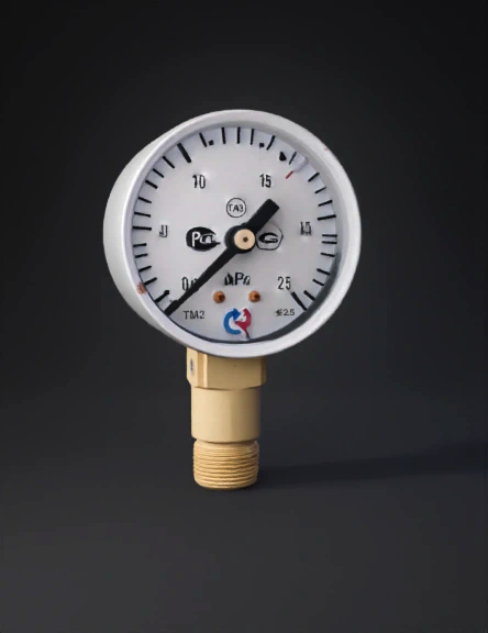
Pressure Gauge 3D Model
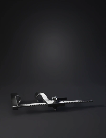
Metal Measuring Gauge 3D Model
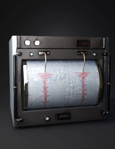
Seismograph 3D Model
Industrial Dial Gauge 3D Model
Digital Thermometer 3D Model
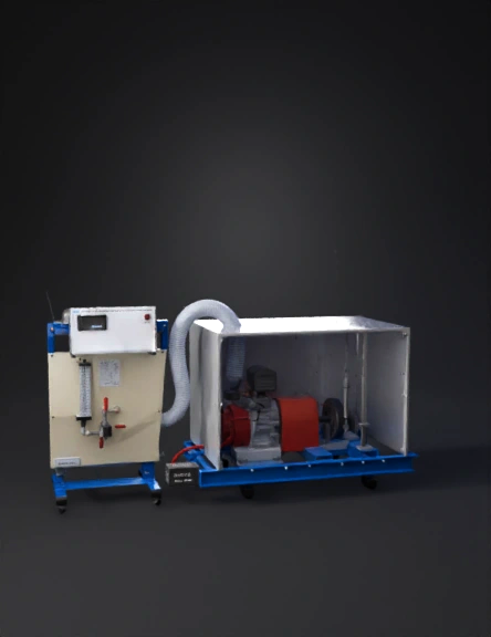
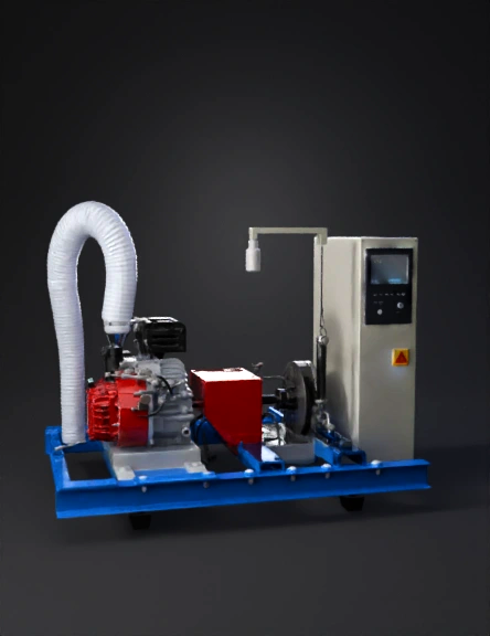
Engine Dynamometer 3D Model
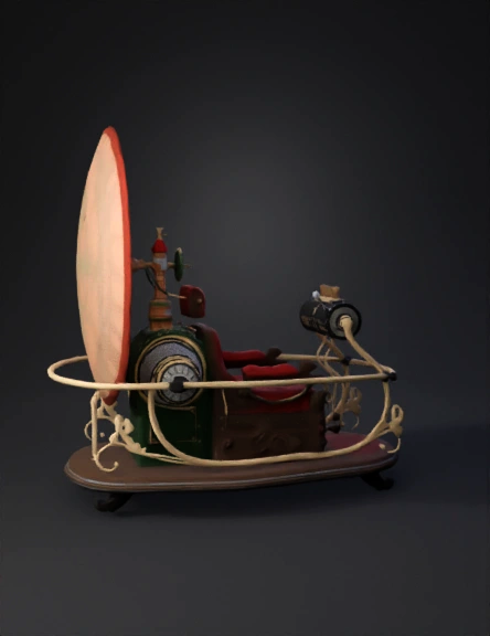
Vintage Gauge Machine 3D Model
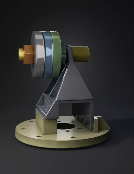
Vintage Gyroscope 3D Model
Engine Dynamometer 3D Model
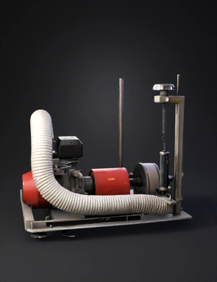
Engine Dynamometer 3D Model
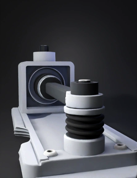
Vibration Damper 3D Model
Dynamometer Lever Arm 3D Model
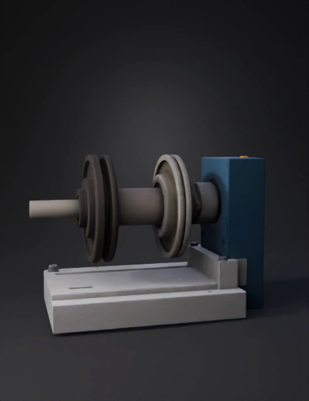
Engine Shaft Assembly 3D Model
Engine Test Bed 3D Model
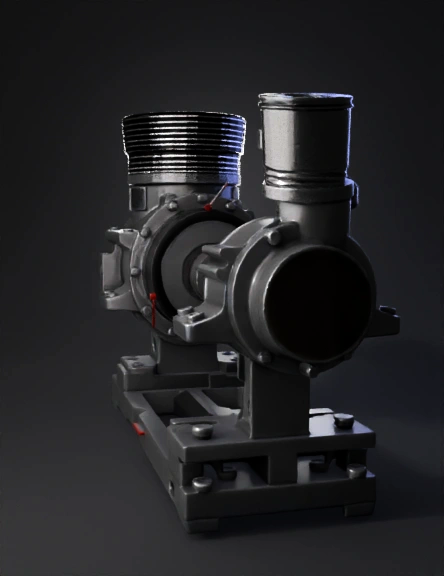
Engine Coupling 3D Model