?
Gantry 3D Models
Find the best Gantry 3D Models, free download in STL, FBX, GLB, OBJ, 3MF, USDZ for 3D modeling and creation in Blender, 3D printing, game developing, animation, eCommerce, AR/VR and etc. Generated by Tripo AI 3D Generator.
You May Also Like :
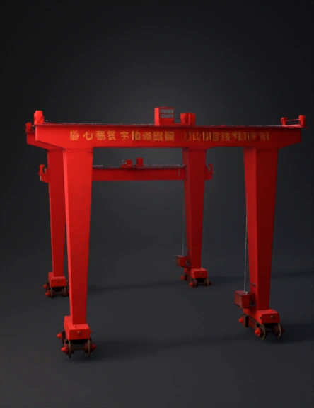
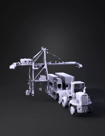
龙门吊 3d 模型 3D Model
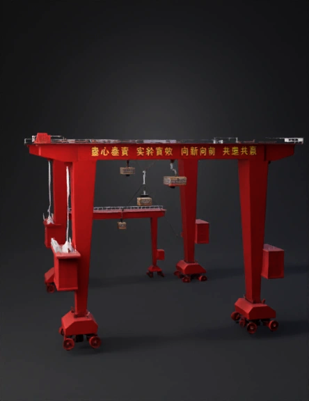
龙门吊3d模型 3D Model
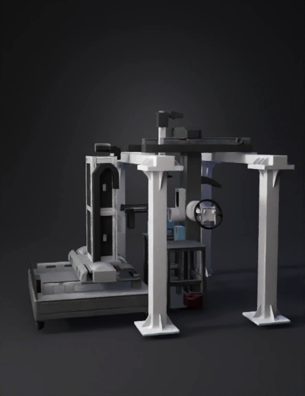
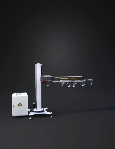
Gantry Machine 3D Model
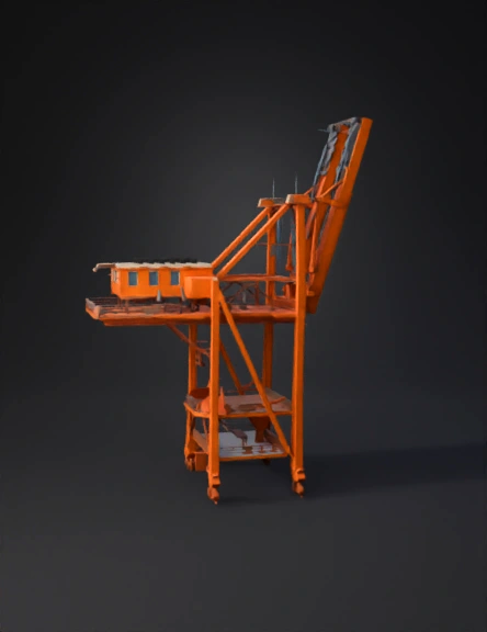
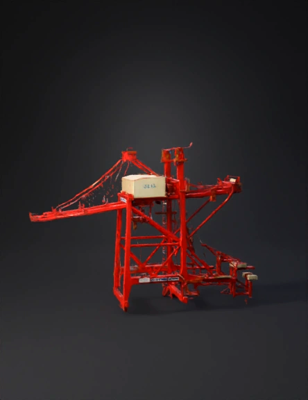
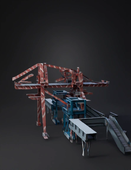
Orange Gantry Crane 3D Model

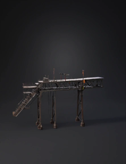
Highway Sign Gantry 3D Model
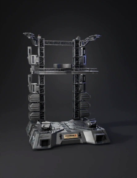
Science Fiction Gantry 3D Model

Gantry Crane 3D Model
Railway Signal Gantry 3D Model

Green Crane 3D Model
Heavy Gantry Crane 3D Model
Large Gantry Crane 3D Model
Industrial Gantry 3D Model

3d Printer Gantry 3D Model
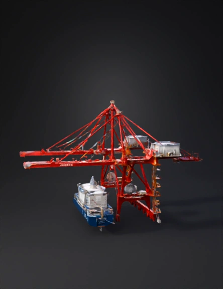
Container Gantry Crane 3D Model

Gold Gantry Crane 3D Model

Gantry Crane 3D Model
Gantry Crane 3D Model

Gantry Frame 3D Model