?
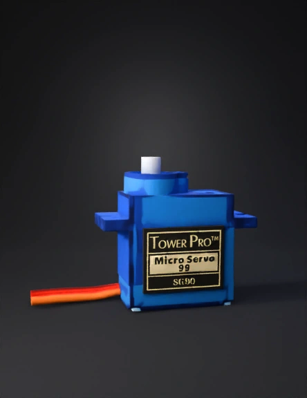
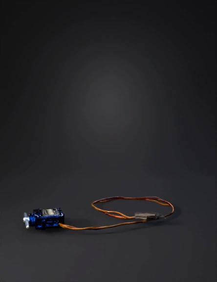
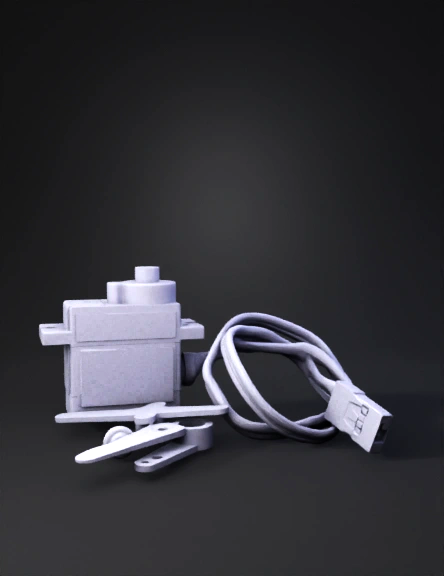
Micro servo 3D Models
Find the best Micro servo 3D Models, free download in STL, FBX, GLB, OBJ, 3MF, USDZ for 3D modeling and creation in Blender, 3D printing, game developing, animation, eCommerce, AR/VR and etc. Generated by Tripo AI 3D Generator.
You May Also Like :
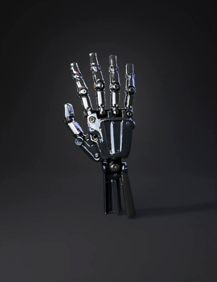
Robotic Hand 3D Model
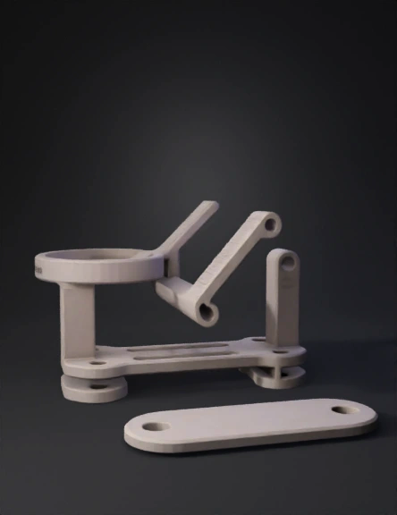
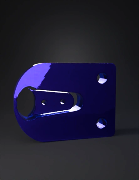
Joystick Servo Bracket 3D Model
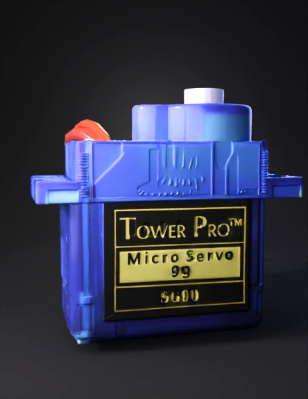
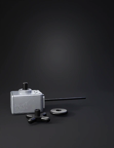
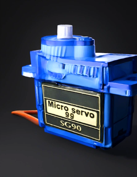
Micro Servo 3D Model
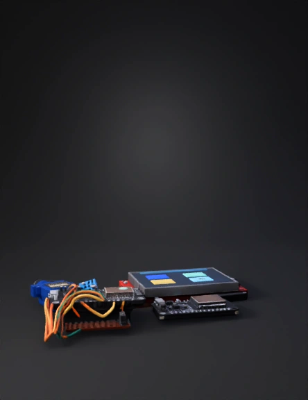
Electronics Prototype 3D Model
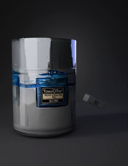
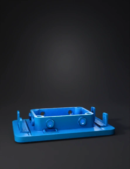
Blue Servo 3D Model
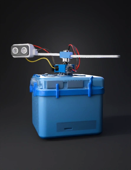
Tiny Robotics Kit 3D Model
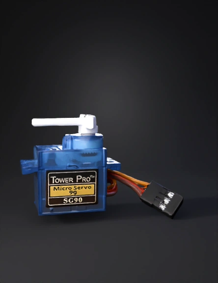
Micro Servo Motor 3D Model
Tower Pro Sg90 3D Model
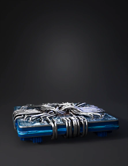
Futuristic Microchip 3D Model
Micro Servo 3D Model
Mechanical Base 3D Model
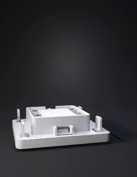
Enclosure Base 3D Model
Micro Servo Motor 3D Model
Mini Servomotor Mount 3D Model
Servo Motor 3D Model
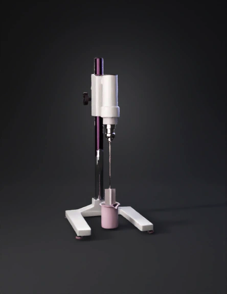
Laboratory Micromanipulator 3D Model
Micro Servo 3D Model
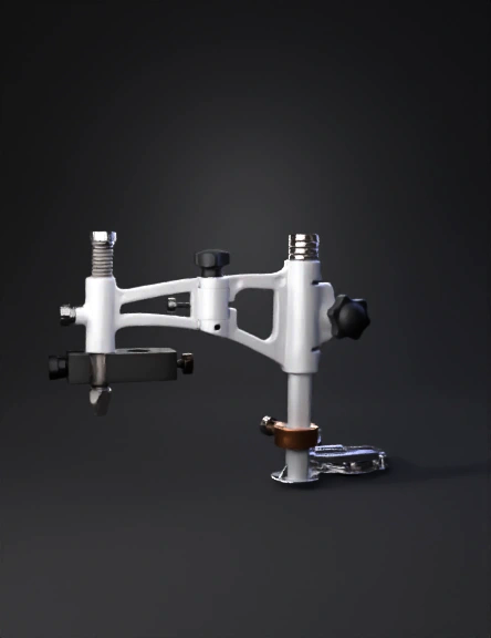
Micromanipulator 3D Model