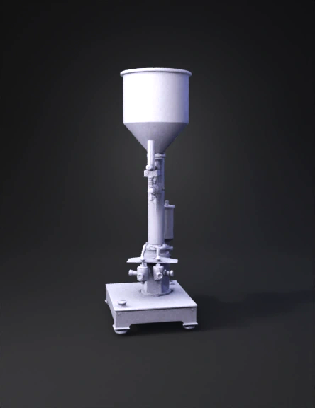
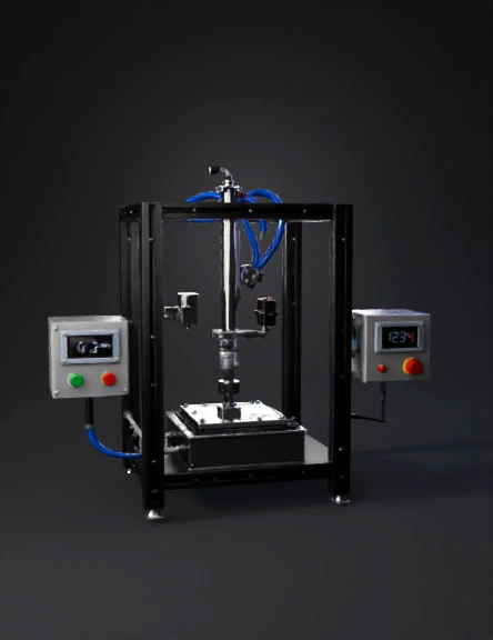
Liquid Filling Machine 3D Model
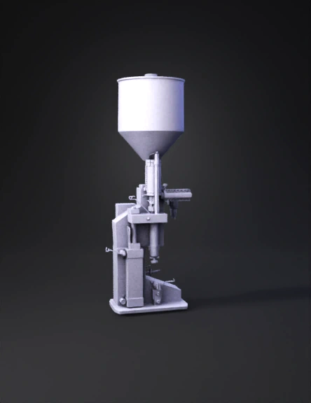
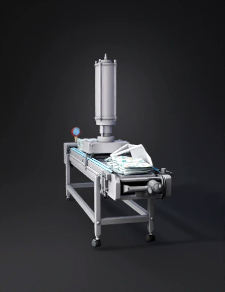
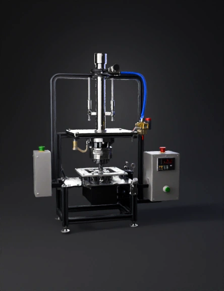
Pneumatic Filler 3D Model
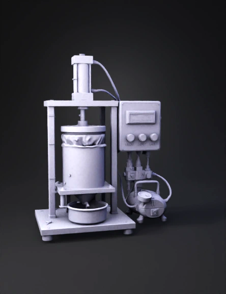
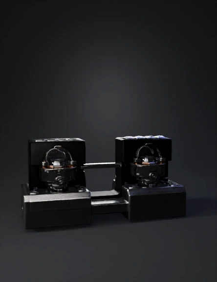
Pneumatic Press Machine 3D Model
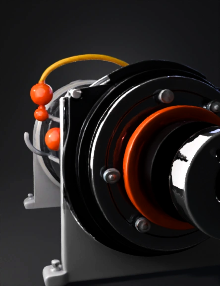
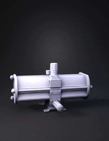
Pneumatic Pulsator 3D Model
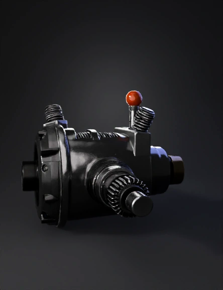
Pneumatic Pulsator 3D Model
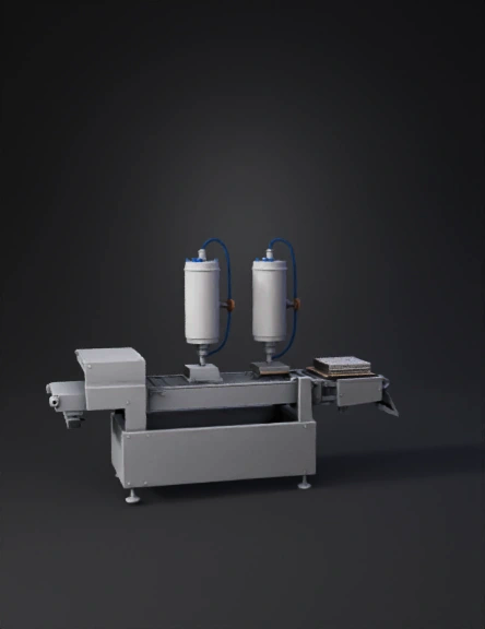
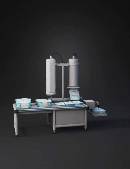
Industrial Packaging Machine 3D Model
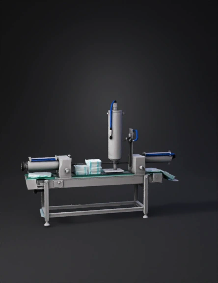
Diaper Packaging Machine 3D Model
Industrial Packaging Machine 3D Model
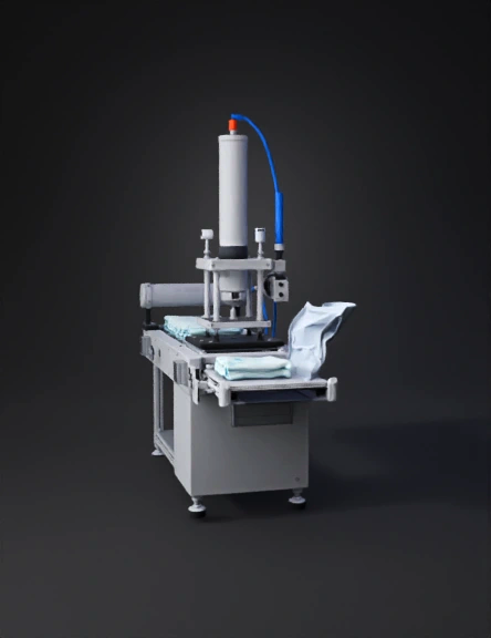
Diaper Packaging Machine 3D Model
Diaper Packaging Machine 3D Model
Diaper Packaging Machine 3D Model
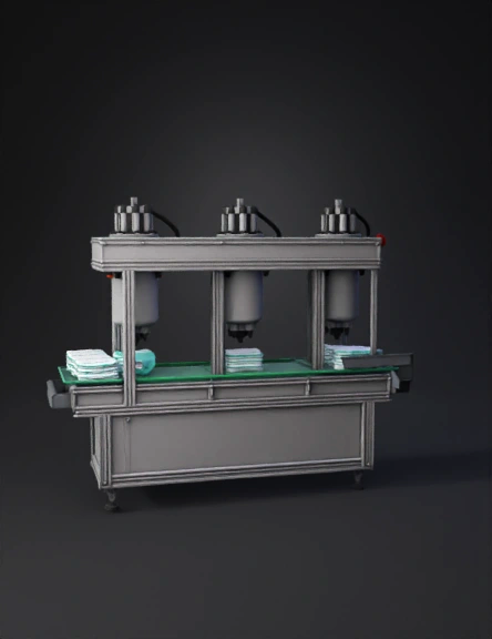
Diaper Packaging Machine 3D Model
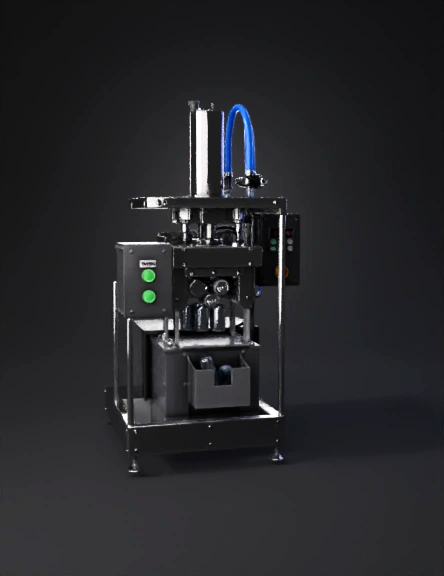
Electro-pneumatic Can Crusher 3D Model
Industrial Can Crusher 3D Model
Industrial Can Crusher 3D Model
Connector Holding Fixture 3D Model
Pneumatic Cylinder 3D Model
Pneumatic Engine 3D Model