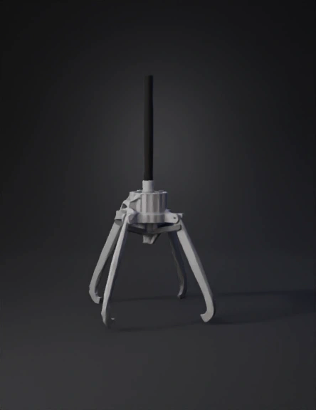
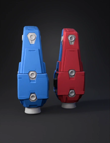
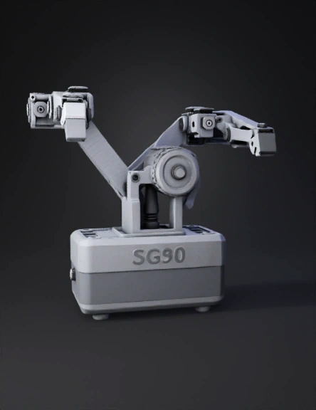
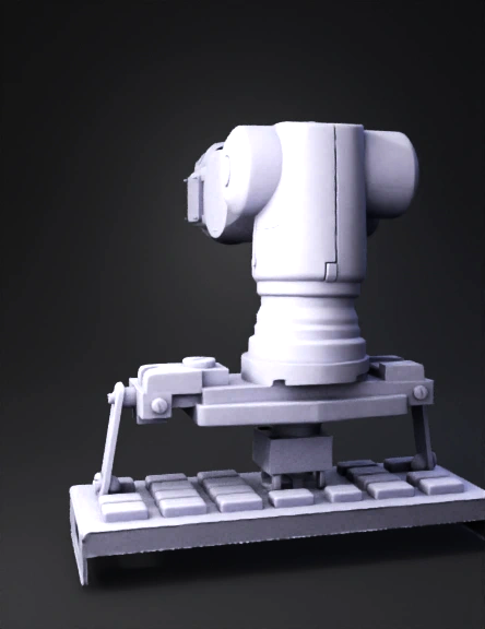
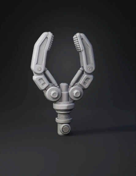
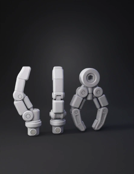
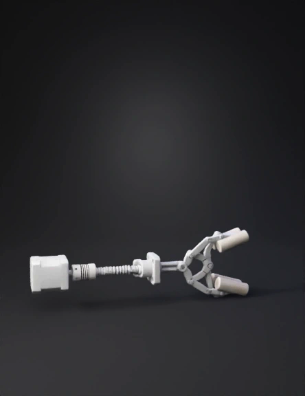
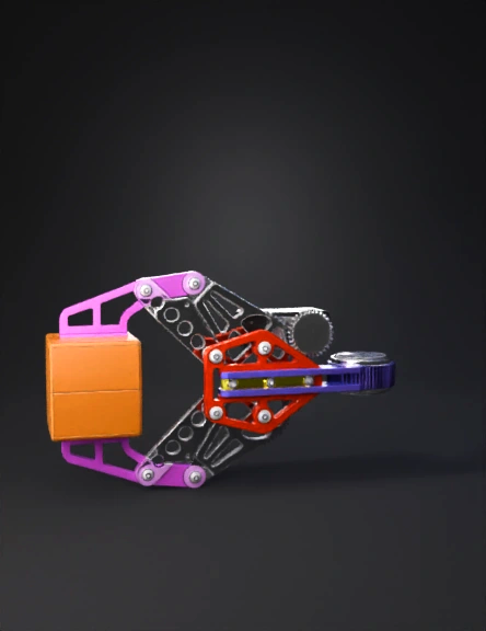
Robotic Gripper 3D Model
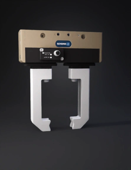
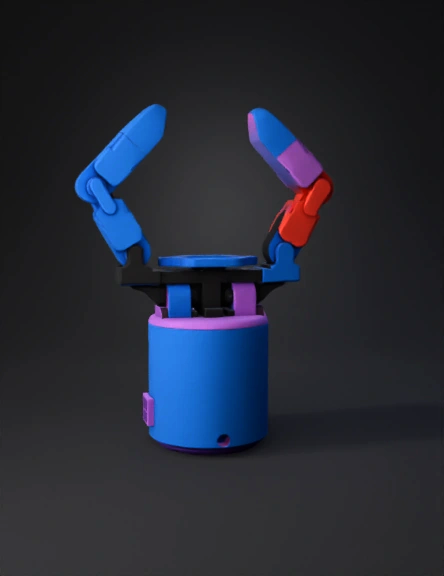
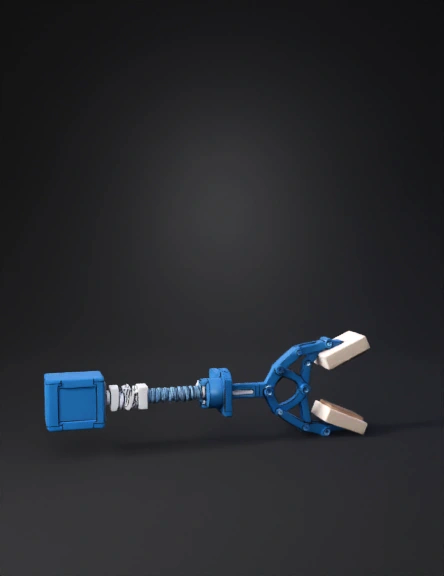
Robotic Gripper 3D Model
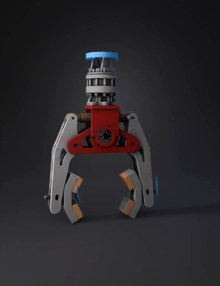
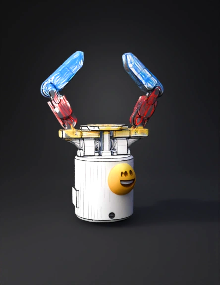
Robotic Gripper 3D Model
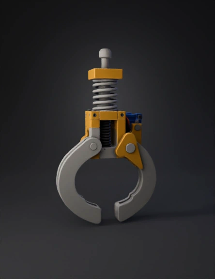
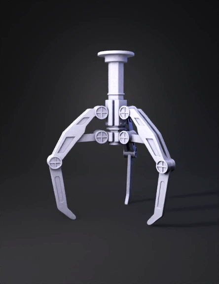
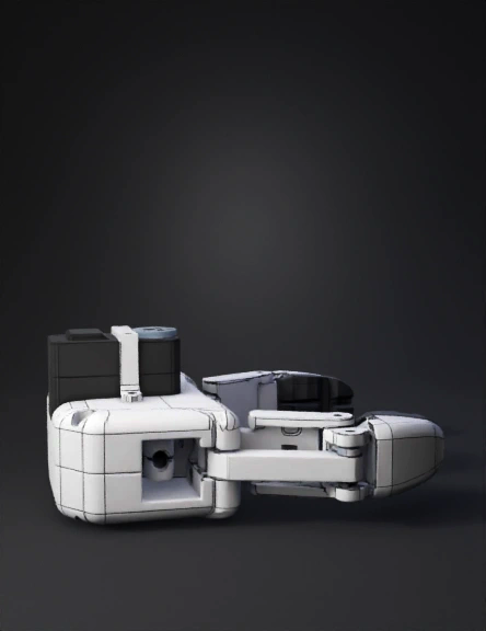
Robotic Gripper 3D Model
Robotic Gripper 3D Model
Robotic Gripper 3D Model
Robotic Gripper 3D Model
Robotic Gripper 3D Model
Robotic Gripper 3D Model

Robotic Gripper 3D Model
Robotic Gripper 3D Model
Robotic Gripper 3D Model
Robotic Gripper 3D Model
Robotic Gripper 3D Model
Robotic Gripper 3D Model
Robotic Gripper 3D Model
Robotic Gripper 3D Model
Robotic Gripper 3D Model