?
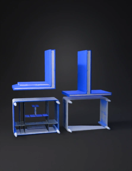
Technical drawing 3D Models
Find the best Technical drawing 3D Models, free download in STL, FBX, GLB, OBJ, 3MF, USDZ for 3D modeling and creation in Blender, 3D printing, game developing, animation, eCommerce, AR/VR and etc. Generated by Tripo AI 3D Generator.
You May Also Like :
Sleeve Component 3D Model
Abstract Logo 3D Model
Acrylic Ruler 3D Model
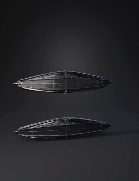
Rc Fishing Boat 3D Model
Bio-forge Pen 3D Model
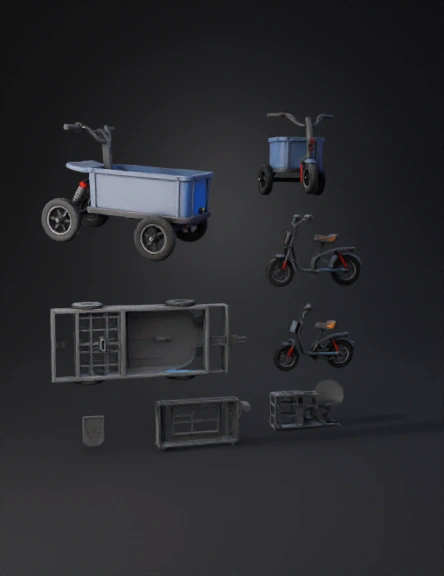
Three-wheeled Cargo Tricycle 3D Model
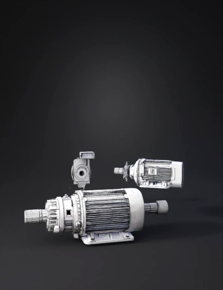
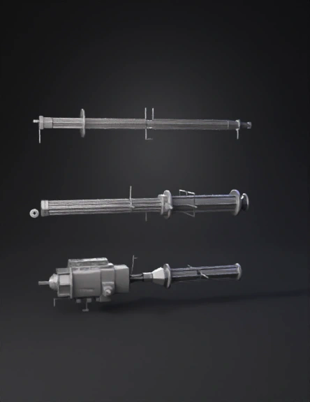
Electric Motor 3D Model
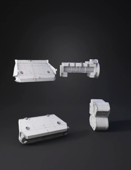
Mechanical Part 3D Model
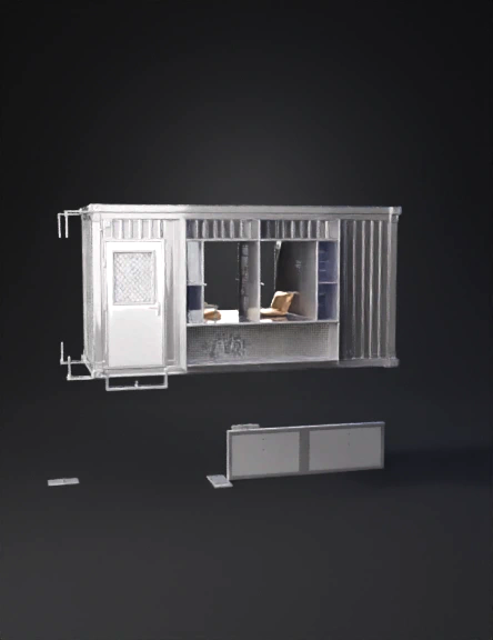
Prefab Office Cabin 3D Model
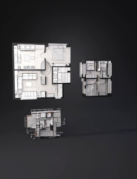
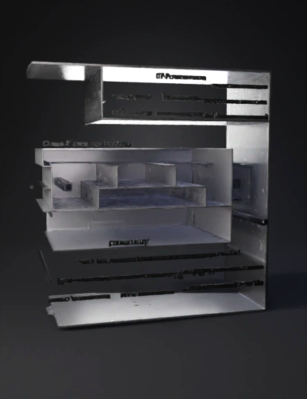
Apartment Design 3D Model

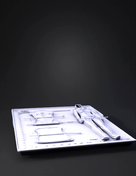
3d Tekne Modeli 3D Model
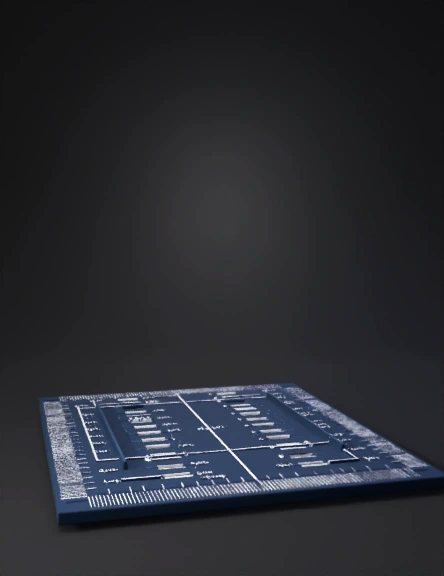
Cartesian Plane Stencil 3D Model
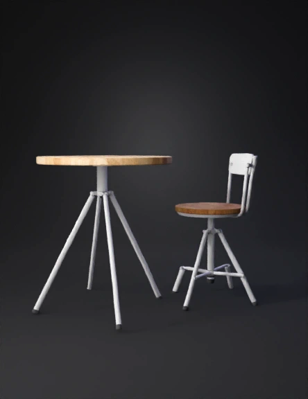
Round Wooden Table 3D Model
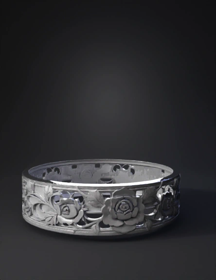
Floral Bracelet 3D Model
Monitor Bracket 3D Model
3d模型六角外框 3D Model
L-shaped Bracket 3D Model
3d Box Model 3D Model