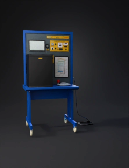
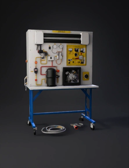
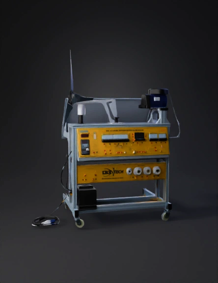
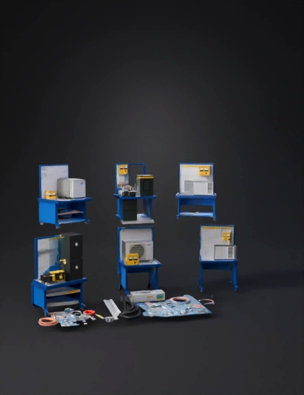
Lab Testing Bench 3D Model
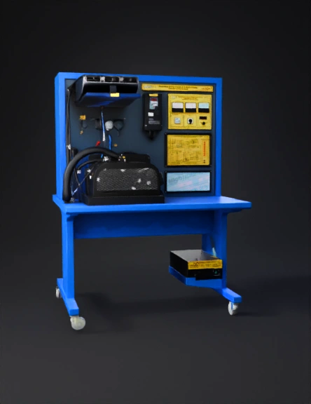
Mechanical Test Rig 3D Model
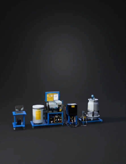
Industrial Test Rig 3D Model
Laboratory Equipment 3D Model
Industrial Machine 3D Model
Industrial Equipment 3D Model
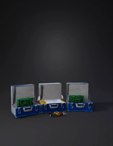
Pcb Testing Kit 3D Model
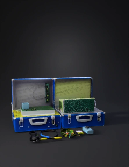
Pcb Testing Kit 3D Model
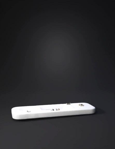
Rapid Test Cassette 3D Model
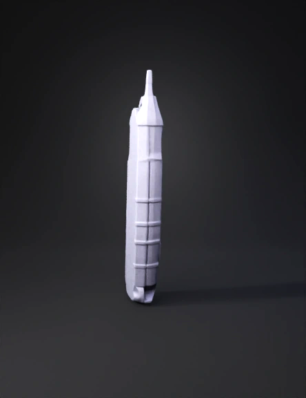
Digital Voltage Tester 3D Model
Industrial Machinery 3D Model
Lab Testing Equipment 3D Model
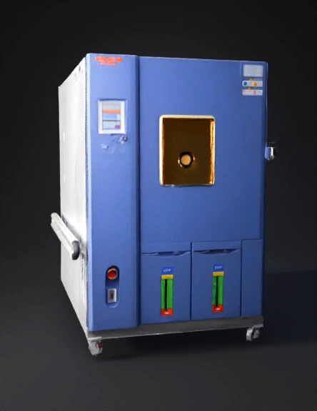
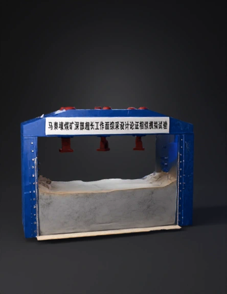
Environmental Test Chamber 3D Model
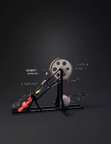
Pulley Testing Rig 3D Model
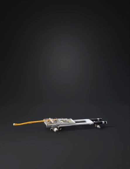
Robotic Test Rig 3D Model
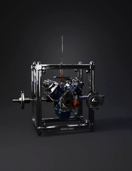
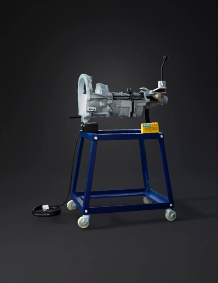
Engine Test Stand 3D Model
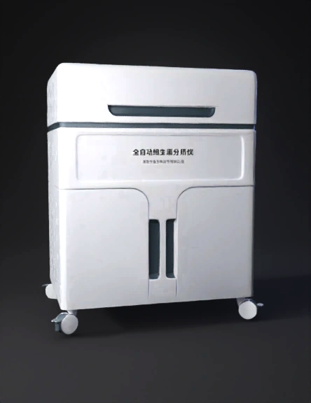
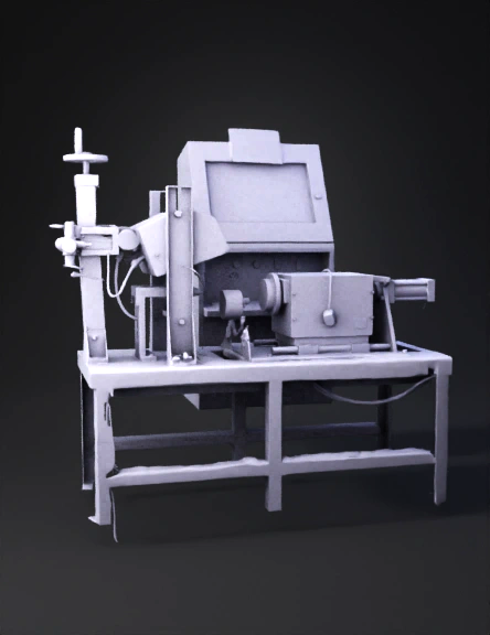
Automatic Lab Analyzer 3D Model
Lab Equipment 3D Model