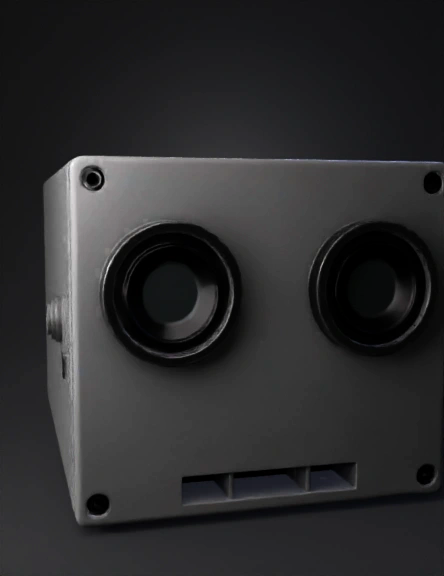
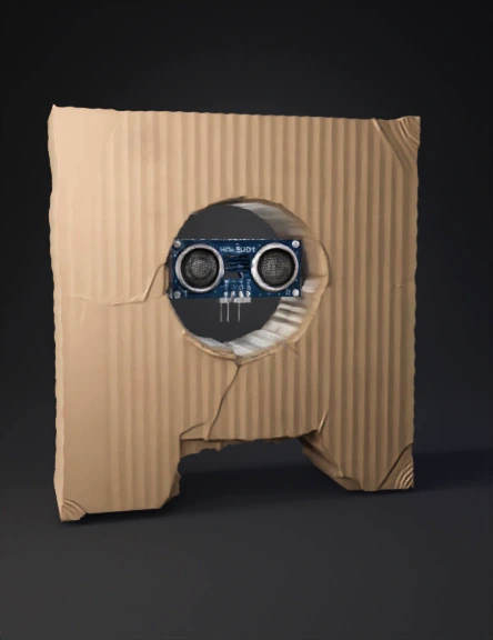
Senzor Ultrasonic 3D Model
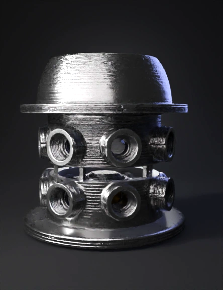
Sensor Crown 3D Model
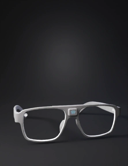
Smart Glasses 3D Model
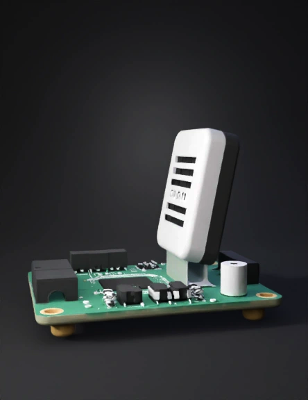
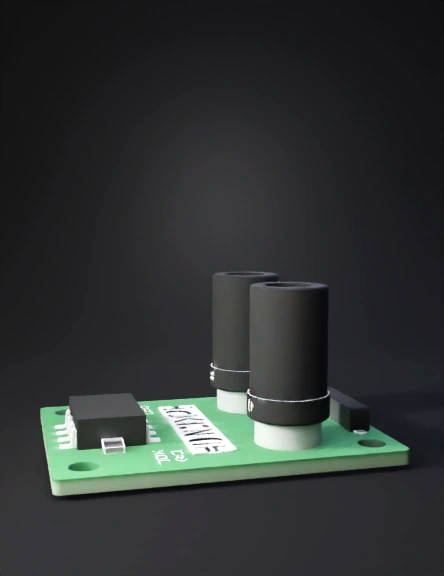
Sensor Prototype 3D Model
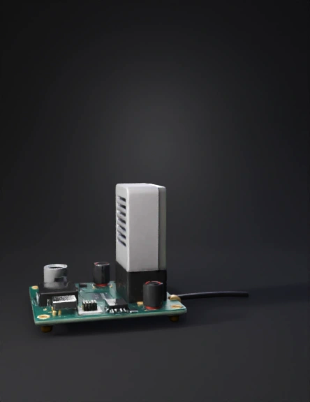
Sensor Prototype 3D Model
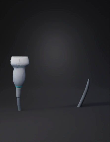
Ultrasound Probe 3D Model
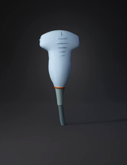
Ultrasound Probe 3D Model
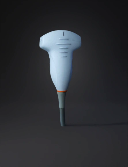
Ultrasound Probe 3D Model
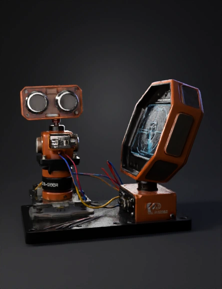
Ultrasonic Radar Detector 3D Model
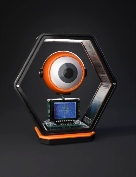
Sci-fi Radar Detector 3D Model
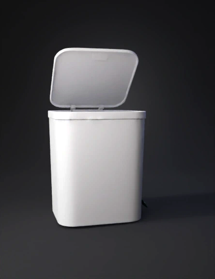
Smart Waste Bin 3D Model
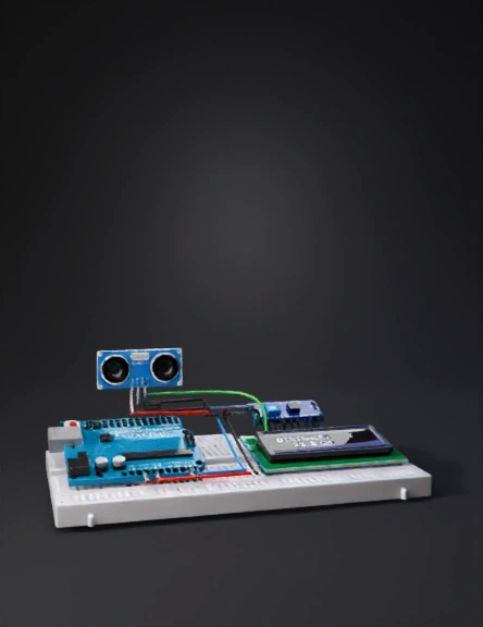
Arduino Project , Make It More Detailed 3D Model
Model 3d Sensor Ultrasonik 3D Model
Ultrasonic Sensor 3D Model
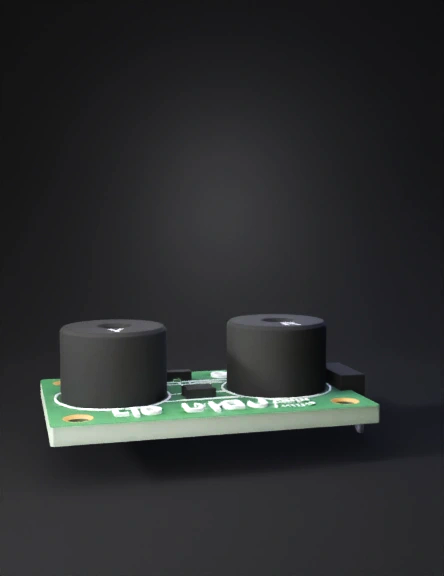
Hc-sr04 Sensor 3D Model
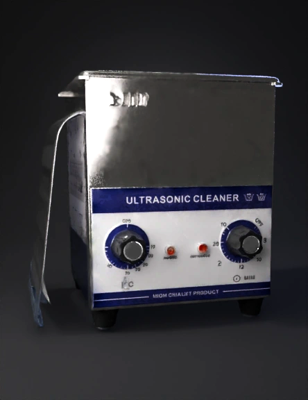
Ultrasonic Cleaner 3D Model
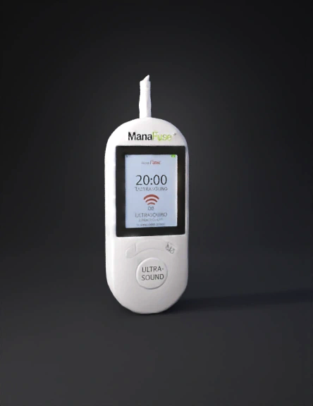
Ultrasound Handheld Device 3D Model
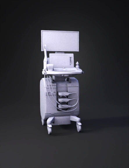
Medical Ultrasound Machine 3D Model