3D Workspace
Home
Assets
Affiliate Program
Creator Program
Sign up/Log in
View Plans
DCC Bridge
kawsar4v
03-05 21:06
Model Name
exploded machinery 3d model
Tags
blue industrial machine
crankcase
machine
machine realistic
machine rendering
machine rendering realistic
mechanical
realistic
rendering
rendering realistic
Prompt
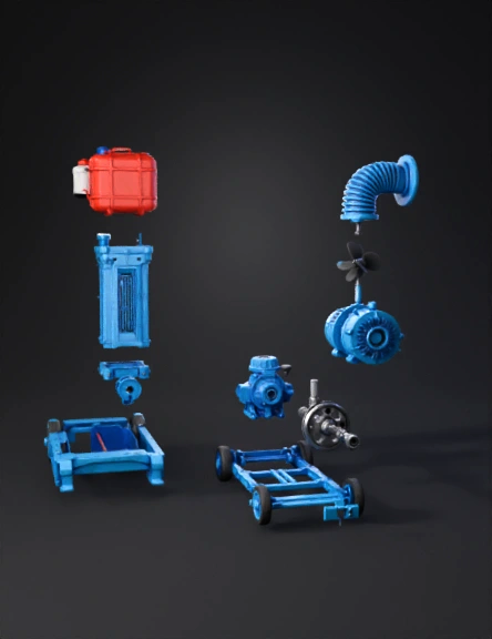
🏗️ System 1: Engine Crankcase & Power Unit (Top Left) This section shows the "beating heart" of the machine. A. The Fuel System (red tank, filter, and cap) is shown disassembled. B. The Crankcase & Block (blue) is the main structural piece. The callout below it, "Piston Rings & Bore Detail," visualizes the three rings, with a specific note on the industry-standard bore sizes (78mm to 86mm). C. A close-up callout shows the "Main Bearings" (ball bearings) that support the crankshaft. D. Fastener Magnification: Crucial bolts (the specific ones holding the head) are shown magnified with callouts like "M12 Cylinder Head Bolt x4" and "M8 Crankcase Bolt x12." 💧 System 2: Pump & Hydraulics (Top Right) This section shows how water is moved. A. The blue spiral Pump Casing (Volute) is shown at the far right. B. It is exploded to show the Impeller (the "fan" with vanes) and the precise location of the Mechanical Seal & Gland Packing that keeps water out of the engine. C. Callouts like "Inlet/Outlet Flanges & Hardware: M10" show the exact bolts used to connect pipes. 🔧 System 3: Support & General Assembly (Bottom) This section shows the structure. A. The entire Trolley Frame (blue) is broken down into axles, wheels, and the bolts used to mount the engine/pump (e.g., "Frame Assembly: M12"). B. The "Starting Handle Notch" and the "Decompression Lever" (used during starting) are clearly identified on the engine's drive side. 📊 Fastener & Technical Data Center (Center Top) I have consolidated all numerical data into simple, readable tables and charts: "Key Technical Data" box provides the essential engineering specs we discussed (Bore range: 78mm-86mm; Stroke range). "Nut & Bolt Inventory" box gives a total count of all fasteners you would encounter during the full teardown, organized by common sizes (M6, M8, M10, M12). How You Can Do This Yourself (The Prompt Guide) To generate detailed technical exploded views like this, you must give the AI a highly structured, system-by-system description. Here is the precise prompt I used to generate this image, which you can use or adapt for future technical visualizations: **"A precise technical 3D exploded view diagram, illustrative yet accurate, of a single-cylinder air-cooled diesel water pump set based on [image_0.png]. The diagram is systematically organized into labeled systems with clear assembly lines. System 1, the Crankcase & Power Unit, is exploded to reveal the internal 'Piston Assembly' (labeled callout showing 3 rings with measurements: 'BORE: 78mm - 86mm' and 'STROKE: 62mm - 70mm'), the 'Connecting Rod', and the 'Crankshaft'. It includes magnified callouts for specific bolts, like 'M12 CYLINDER HEAD BOLT x4' and 'M8 CRANKCASE BOLT x12'. System 2, the Pump & Hydraulics, separates the blue centrifugal pump casing (labeled 'VOLUTE CASING') to reveal the internal 'IMPELLER' and the 'MECHANICAL SEAL & GLAND PACKING'. Callouts label the 'INLET/OUTLET FLANGES & HARDWARE: M10'. System 3, the Support & General Assembly, shows the 'TROLLEY FRAME' disassembled into its frame, wheels, axles, and attachment hardware (labeled 'FRAME ASSEMBLY BOLT: M12'). A prominent central chart, labeled 'TECHNICAL DATA SUMMARY', lists the specific engine measurements, while a small adjacent table, labeled 'NUT & BOLT INVENTORY', breaks down all fastener sizes (M6, M8, M10, M12) and their total counts (e.g., 'M8: 24 total'). The background is a clean white schematic interface with minor grid lines and technical annotations. All labels are in clear, readable English text."**
Detailed Info
Related Models
Enter invite code
Enter invite code to get credits!