3D Workspace
Home
Assets
Affiliate Program
Creator Program
Sign up/Log in
View Plans
DCC Bridge
mohamahm168
02-23 12:00
Model Name
smart glasses 3d model
Tags
glass
props
props realistic
props rendering
props rendering realistic
realistic
rendering
rendering realistic
smart glasses
Prompt
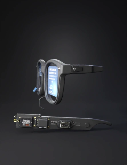
🔬 Materials & Their Exact Role in the Smart Glasses 🔵 RIGHT LENS — The Question Display Material: 0.96" OLED Display (SSD1306, I2C, 128×64 pixels) This tiny screen is mounted inside the right lens rim, angled slightly inward toward your eye at about 15 degrees. It shows the text of whatever question the person in front of you just asked. Why this specific one? It runs on 3.3V, draws only 20mA, is 0.96 inches — small enough to sit in the corner of a lens without blocking vision, and communicates over just 2 wires (I2C). Exact position: glued with UV-cure optical adhesive to a small 3D-printed bracket inside the right lens rim, upper-inner corner, facing the pupil. Material: Transparent Acrylic Lens (2mm, optical grade) Acts as the actual "glass" of the right lens. The OLED image reflects off a tiny beam-splitter prism placed between the display and this lens, overlaying the text on your real-world view. Exact position: fills the right lens opening of the frame, cut to shape with laser cutter or ordered custom. Material: Beam Splitter Prism (5mm × 5mm) A tiny half-mirror cube. Light from the OLED hits it and bounces 90 degrees toward your eye. At the same time, light from the world passes straight through it, so you see both the text AND what's in front of you simultaneously. Exact position: mounted directly in front of the OLED on the right lens bracket, at 45 degrees to both the OLED and your eye line. 🟣 LEFT LENS — The Private Answer Display Material: 0.96" OLED Display (SSD1306, I2C, 128×64 pixels, address 0x3D) Identical to the right one but set to a different I2C address so both can run on the same 2-wire bus simultaneously. Shows the AI-generated answer — only to you. Exact position: mounted in the left lens rim, upper-inner corner, same bracket design as right side. Material: Linear Polarizer Film (45-degree, 0.2mm thick) A thin optical film laminated directly onto the face of the left OLED display using optical adhesive. It polarizes the light emitted by the OLED at a 45-degree angle. Exact position: stuck flat on top of the left OLED glass face before mounting in the frame. Material: Analyzer Polarizer Film (matching 45-degree, 0.2mm thick) The matching pair to the film above. Must be cut from the same sheet and oriented at the same angle. Laminated to the inner surface of the left lens itself. When your eye looks through this film at the OLED (which also has the same film), the image is sharp and bright. Anyone looking from the outside sees darkness because they are not aligned with both layers. Exact position: laminated to the inner face of the left acrylic lens. Material: Collimator Micro-Lens (f=8mm, 8mm diameter, aspheric) A tiny focusing lens placed between the OLED and the beam-splitter. Narrows the light cone from 170 degrees down to ~35 degrees. This is what stops the person sitting next to you from seeing your answer even if they look sideways at your lens. Exact position: press-fitted into the lens bracket, between the OLED face and the beam-splitter prism. Material: Beam Splitter Prism (5mm × 5mm) — same type as right lens Same function as right side: overlays the answer text onto your real-world view. Exact position: same bracket placement as the right lens, on the left side. 🌉 BRIDGE — The Brain of the Glasses Material: Raspberry Pi Zero 2W The main computer. Runs the Python software, controls both OLEDs, processes audio, calls the AI API. It is a full Linux computer the size of a stick of gum (65mm × 30mm × 5mm). Exact position: embedded inside the LEFT temple arm, which is 3D printed slightly wider (16mm) to accommodate it. Secured with double-sided thermal foam tape to manage heat. Material: INMP441 I2S MEMS Microphone (breakout board, 10mm × 10mm) An ultra-small, high-sensitivity digital microphone. Captures everything within about 2 meters in front of you clearly. Uses I2S protocol — a digital audio interface — which avoids the analog noise you'd get with a standard mic. Exact position: embedded in the FRONT of the bridge (the center piece between the two lenses), with the mic hole pointing forward. A tiny 1mm hole is drilled through the 3D print for sound entry. ⚡ RIGHT TEMPLE — The Power Bank Material: LiPo Battery (3.7V, 1000mAh, thin flexible type, ~60mm × 35mm × 4mm) Powers the entire system. The thin flexible form factor is essential — it bends slightly to fit inside the curved temple arm. Exact position: runs along the full length of the RIGHT temple arm inside a snug channel in the 3D print. Held in with a thin foam pad. Material: TP4056 Charging Module (USB-C version, 20mm × 15mm) Manages safe charging and discharging of the LiPo. Without it, overcharging would destroy the battery or cause fire. Has built-in over-charge, over-discharge, and short-circuit protection. Exact position: at the HINGE END of the right temple, near where the USB-C port exits through the frame. The USB-C port itself peeks through a small slot in the 3D print. Material: MT3608 Boost Converter Module (18mm × 11mm) Steps the battery's varying voltage (3.7V–4.2V) up to a stable, clean 5.0V for the Raspberry Pi. The Pi will crash if voltage drops below 4.75V — this prevents that. Exact position: soldered to the output of the TP4056, sitting right next to it inside the right temple. 🖼️ FRAME — The Shell Material: PETG Filament (1.75mm, matte black) The entire glasses frame is 3D printed from PETG. Why PETG over PLA? It tolerates heat better (important near the Pi), has slight flexibility so hinges don't snap, and is more skin-safe for long wear. The frame is printed in 5 parts: left temple, right temple, bridge, left lens rim, right lens rim — then assembled with M2 screws and hinge pins. Printed wall thickness: 1.2mm outer walls, 2mm around electronics cavities for structural strength. Material: M2 × 6mm Stainless Steel Screws + M2 Brass Heat-Set Inserts Used to assemble the temple-to-rim connections and secure the electronic modules inside. Heat-set inserts are pressed into the PETG with a soldering iron — they create strong reusable threaded holes in plastic. Exact position: 2 inserts per temple junction, 1 per OLED bracket. Material: Spring Steel Hinge (standard glasses hinge, 5-barrel, 14mm) Standard off-the-shelf glasses hinges. Gives the temples their open/close action and makes the glasses wearable like normal eyewear. Exact position: embedded into both temple-to-rim joints, glued with epoxy and reinforced by the M2 screws. 🔌 WIRING Material: 30 AWG Silicone-Insulated Wire (multi-strand) Connects everything together. Silicone insulation is flexible and doesn't crack when the temples flex open and close, unlike PVC wire which becomes brittle. Colors used: red = 5V power, black = ground, yellow = SDA, blue = SCL, white = I2S data lines. Routing path: wires run from the Pi in the left temple through a 1.5mm channel in the bridge to the microphone, then branch to both lens rims for the OLEDs. Material: JST PH 2.0mm 2-Pin Connector (pair) A tiny locking connector used between the battery and the TP4056 module. Makes the battery detachable for replacement without soldering. Exact position: at the battery output leads inside the right temple. 🔘 CONTROLS Material: 6mm Tactile Push Button (low-profile, 3.5mm height) Two buttons: one for power on/off, one for mode switching (e.g. switch between AI models or mute mode). Exact position: both buttons are recessed into the TOP SURFACE of the bridge, accessible by your fingertip without removing the glasses. Material: RGB LED (3mm, common cathode) Shows system status: green = ready, blue = listening, yellow = processing, red = low battery. Exact position: on the INNER FACE of the bridge, pointing slightly downward so only the wearer can see the glow — not visible to others from the front.
Detailed Info
Related Models
Enter invite code
Enter invite code to get credits!