3D Workspace
Home
Assets
Affiliate Program
Creator Program
Sign up/Log in
View Plans
DCC Bridge
Anonymous1770813129
02-11 12:43
Model Name
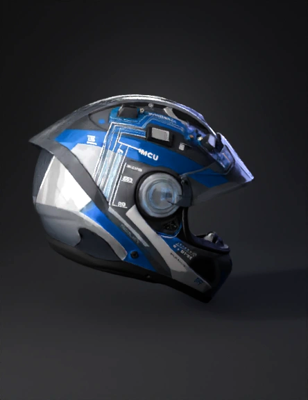
full-face helmet 3d model
Tags
full face helmet
props
props realistic
props rendering
props rendering realistic
realistic
rendering
rendering realistic
Prompt
0️⃣ Helmet Base Assumption Type: Full-face helmet Shell Material: ABS or Polycarbonate Inner Layer: EPS (Expanded Polystyrene foam) Comfort Layer: Removable foam padding We will NOT damage structural safety areas. Electronics must sit: Between comfort padding and EPS Or inside custom shallow cavities in EPS (max 5–7 mm depth) 1️⃣ COMPONENT PLACEMENT OVERVIEW (Top View Layout) 🔹 Crown Area (Top Inside Helmet) → Main Microcontroller Unit (MCU) 🔹 Left Inner Side (Above Ear Area) → Bluetooth Module 🔹 Rear Lower Section (Back of Helmet) → Rechargeable Battery Pack 🔹 Front Upper Forehead Pad → Pressure Sensor (FSR) 🔹 Chin Strap Area → Magnetic Reed Switch / Micro Switch 2️⃣ EXACT COMPONENT POSITIONING (VERY SPECIFIC) 🧠 A. Microcontroller Compartment (Main Control Unit) Component: Arduino Nano / ESP32 Board Size: Approx 45mm x 18mm 📍 Placement: Position at the crown center (top inner area) Between EPS foam and removable comfort padding Horizontal orientation USB port facing rear-left side (for access) 📐 Mounting Method: Create rectangular cavity in EPS: Depth: 6 mm Width: 50 mm Length: 25 mm Secure using: Thin ABS housing box (custom 3D printed) Double-sided 3M industrial tape Optional: Velcro layer for removability ⚠️ Important: Do NOT weaken EPS thickness more than 10%. 📡 B. Bluetooth Module Placement Component: HC-05 or ESP32 built-in antenna 📍 Placement: Left inner wall Just above ear cavity Antenna side facing outward (toward shell) 📐 Mounting: Small 30mm x 20mm cavity in EPS Cover with thin plastic casing Ensure no metal shielding nearby Reason: Helmet shell is plastic → good RF transmission. 🔋 C. Battery Pack Compartment Component: 3.7V Li-ion 18650 or 1000–2000mAh LiPo 📍 Placement: Back lower section of helmet Near occipital region (rear bottom) Reason: Balances weight Keeps center of gravity low Reduces neck strain 📐 Mounting: Create rectangular slot: 70mm x 22mm x 22mm (for 18650) Use battery holder casing Add: Foam vibration dampener Protective insulation wrap Include: Charging port exposed via: Small rubber-sealed port near rear bottom edge 🎯 D. Pressure Sensor (FSR) Placement Component: Thin Force Sensitive Resistor 📍 Placement: Inside forehead comfort pad Between: Head surface ↔ foam pad 📐 Mounting: Sensor diameter: 15–20mm Embed inside soft foam Route thin flexible wire upward along EPS groove Purpose: Detect head contact pressure. Optional: Add second FSR on rear padding for dual confirmation. 🔐 E. Strap Lock Detection System Option 1: Magnetic Reed Switch Option 2: Micro-limit switch 📍 Placement: Inside chin strap locking mechanism. Method: Attach: Small neodymium magnet on buckle tongue Reed switch inside strap housing When strap closes: Magnet aligns → circuit closes. Wiring: Route thin wire along: Strap inner fabric channel → left side → MCU. 3️⃣ INTERNAL WIRING ROUTING (VERY IMPORTANT FOR 3D MODEL) Use 28–30 AWG flexible silicon wires. Wire Path Design: Pressure Sensor → Crown → MCU Strap Sensor → Left Wall → Crown → MCU Bluetooth → Crown → MCU Battery → Rear → Crown → MCU Wiring Channels: Create 3mm wide grooves inside EPS foam. Grooves must: Follow curvature Avoid impact zones Be covered with thin insulating tape No loose wires allowed. 4️⃣ PROTECTIVE CASING DESIGN All electronics must be placed inside: Custom 3D printed ABS enclosures: Thickness: 1.5 mm Ventilation holes: 2–3 small holes Rounded edges to avoid sharp pressure points 5️⃣ SAFETY CONSIDERATIONS Very important for director meeting: Electronics must not interfere with impact absorption zones. No rigid structure directly touching skull. All modules must be cushioned. Battery must include: Overcharge protection Short circuit protection 6️⃣ WEIGHT DISTRIBUTION CALCULATION Electronics total weight approx: Arduino: 7g Bluetooth: 4g Battery: 40g Wires + casing: 20g Total added weight: ~70g That is acceptable for helmet. 7️⃣ POWER SYSTEM DESIGN Battery → TP4056 Charging Module Charging Port → Micro USB (rear bottom) Operating Voltage: 3.7V battery Boost to 5V if required for MCU
Detailed Info
Related Models
Enter invite code
Enter invite code to get credits!