3D Workspace
Home
Assets
Affiliate Program
Creator Program
Sign up/Log in
View Plans
DCC Bridge
venevarsh
12-18 05:16
Model Name
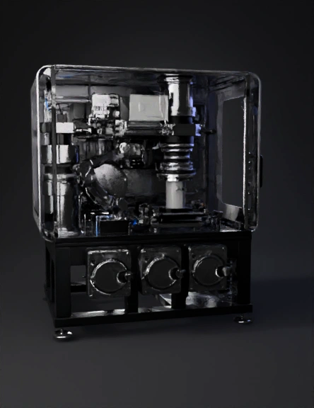
industrial 3d printer
Tags
industrial printer
machine
machine realistic
machine rendering
machine rendering realistic
realistic
rendering
rendering realistic
wafer
Prompt
1. Front-End Wafer Handling Module (FOUP Interface) At the front of the tool, FOUP load ports receive 300 mm wafers in sealed pods. Each load port includes: FOUP docking mechanism Door opener system Wafer ID and orientation sensors Once docked, wafers are transferred into the tool without exposure to ambient air. 3D model note: Show FOUP ports aligned horizontally with robotic access arms behind them. 2. Atmospheric Wafer Transfer Robot Inside the atmospheric section: A dual-blade robotic arm retrieves wafers from the FOUP Wafers are centered and oriented using edge sensors The robot places wafers into a vacuum load-lock chamber This robot operates with micron-level positional accuracy. 3D motion: Rotating arm → extend → pick wafer → retract → rotate → place into load lock. 3. Load Lock & Vacuum Transition Chamber The load lock isolates the cleanroom from the exposure chamber. Functions: Pumps down from atmospheric pressure to high vacuum Removes moisture and particles Matches pressure for the exposure environment Once vacuum is stabilized, wafers move into the internal vacuum transport system. 3D detail: Animated pressure change + sliding vacuum gate valve. 4. Internal Vacuum Wafer Transport System Inside the tool, wafers are transferred using: Linear magnetic tracks or robotic wafer handlers Contact-free handling to prevent contamination The transport system delivers wafers to: Alignment stage Exposure stage Post-exposure transfer ports 5. Reticle (Mask) Handling System Above the wafer plane is the reticle stage, which holds the photomask. Key components: Reticle storage cassette Reticle transfer robot Electrostatic reticle chuck The reticle contains the circuit pattern and is positioned with nanometer precision. 3D note: Place reticle system above wafer stage, separated by projection optics. 6. Illumination Source Module DUV Systems: Excimer laser (193 nm ArF) Beam conditioning optics Uniformity control lenses EUV Systems: High-power CO₂ laser Tin droplet plasma source (13.5 nm) Collector mirrors The light is shaped, stabilized, and directed toward the mask. 3D animation: Laser → beam shaping → mask illumination. 7. Projection Optics Column Between the reticle and wafer is the projection optics system. DUV: Multi-element refractive lenses EUV: Multilayer reflective mirrors This system reduces and projects the reticle pattern onto the wafer with extreme resolution. Critical detail: No physical contact—only controlled photon projection. 8. Wafer Exposure Stage (Core of the Tool) The wafer sits on an electrostatic chuck mounted on a high-speed precision stage. Features: Nanometer-scale positioning Vibration isolation Interferometer-based position feedback The stage performs: Step-and-scan motion Synchronized movement with reticle stage Sub-nanometer alignment corrections This is where the actual pattern transfer occurs. 3D motion highlight: Simultaneous wafer scan + reticle scan during exposure. 9. Alignment & Metrology Subsystem Before exposure: Alignment marks on the wafer are scanned Optical sensors correct X, Y, Z, tilt, and rotation Overlay errors are compensated in real time This ensures each layer aligns perfectly with previous layers. 10. Post-Exposure Wafer Handling After exposure: Wafer is transferred back through vacuum transport Moves into load lock Pressure returns to atmospheric Robot places wafer into FOUP The wafer then goes to: Post-exposure bake Development Etch or deposition steps 11. Environmental Control & Isolation The entire system includes: Active vibration isolation platforms Thermal control within ±0.01 °C Purged nitrogen environments Acoustic and electromagnetic shielding Summary for 3D Model Creation For a correct 3D working model, show: FOUP ports and atmospheric robot Load lock and vacuum transition Reticle system above wafer plane Illumination source → optics → wafer Dual moving stages (reticle + wafer) Vibration-isolated base frame
Detailed Info
Related Models
Enter invite code
Enter invite code to get credits!