3D Workspace
Home
Assets
Affiliate Program
Creator Program
Sign up/Log in
View Plans
DCC Bridge
gabrielmkt.supradiesel
12-04 12:23
Model Name
industrial cnc machine 3d model
Tags
cnc machine
equipment
industrial cnc machine
machine
machine realistic
machine rendering
machine rendering realistic
realistic
rendering
rendering realistic
Input
Prompt
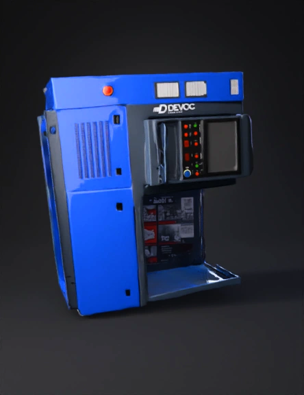
1 — General Overview Industrial bench-top testing equipment with a closed steel cabinet structure, featuring blue (outer panels) and dark-gray (control section) electrostatic coating. The unit sits on a rigid metal base concealed by exterior panels and is currently placed on a wooden pallet for transport. It includes a front control console (screen/buttons) and a right-side test chamber with a hinged door and glass/acrylic window. The “DEVOC” logo appears prominently on the lower-right front panel and vertically on the central left column. 2 — Approximate Dimensions (for initial 3D scaling) Note: Dimensions below are ESTIMATED from the photo. Replace with precise measurements when available. Total height: ≈ 1500–1700 mm Total width: ≈ 1400–1700 mm Depth: ≈ 700–900 mm Console (screen) height from floor: ≈ 900–1100 mm Sheet-metal thickness: 1.5–3 mm (folded steel panels) All modeling should be done at real-world scale (1:1) in millimeters. 3 — External Structure (Face-by-Face Description) Front View Lower front panel: Large blue section with a rectangular ventilation grille (thin horizontal openings). Two separate lower access doors with small recessed finger grips. Central vertical column (dark gray): “DEVOC” letters applied vertically in white. This column houses the control console. Control console: Rectangular monitor with dark-gray frame and glossy glass surface. Button panel below the monitor: Green and red round push buttons, small red LED numeric displays, indicator lights, and a large emergency stop mushroom button (yellow base, red top). Pull-out tray/mini-desk containing a mouse/USB area. Right test-chamber door: Dark-gray metallic frame. Large central glass/acrylic window. Hinged on the right side (door is open in the photo). Rubber gasket around the door edges. Left Side Large blue panel with industrial safety stickers (yellow/black rectangles). A big rotary emergency/power switch (red handle, yellow square base). Small data/specification plate at the upper section. Top View Slightly angled front section. Seam lines suggest removable top cover with concealed screws. Base / Bottom Internal metal supports and mounting rails; sitting on a pallet in the photo. Likely includes adjustable feet or anchor points. 4 — Test Chamber (Interior Details Visible in the Photo) Door assembly: metal frame, glass center, latch mechanism, vertical hinge. Internal working platform: A flat red metal plate used for mounting injectors/pumps. Rotating test plate / fixture system: Circular or partially circular plate with multiple clamp points. Connected to hoses and actuators. Cylinders/solenoids: Small silver pneumatic/hydraulic actuators visible on upper right area. Tubing system: Combination of steel pipes and flexible hoses (rubber/PTFE) with threaded fittings. Sensors / transducers: Small boxed modules with cables routed toward the electronics compartment. Guides & supports: Metal profiles, angled brackets, and bolted fixtures. 5 — Panels, Doors & Mechanical Features Panel corners: 3–6 mm filleted radius (typical folded steel). Gaps between panels: 5–8 mm spacing. Screw types: Philips or hex, typically around access openings. Ventilation grille: stamped/laser-cut metal sheet. Paint: Electrostatic coating, glossy for blue, matte/semi-gloss for gray. 6 — Recommended Materials & PBR Textures Outer panels (blue): Painted steel — Roughness: medium-low Metallic: 0–0.1 Console frame (dark gray): Matte painted steel. Window frame: Steel or anodized aluminum. Glass: IOR ≈ 1.5 Subtle reflections and fingerprints for realism. Push buttons: glossy plastic. Hoses: medium-rough rubber, metallic clamps. Screws/bolts: stainless steel (Metallic = 1.0). Decals (logo, warnings): Vinyl stickers with slight edge thickness via normal map. 7 — Recommended Mesh Organization (Naming Convention) Main groups: base_frame panel_left, panel_right, panel_front_lower, panel_front_upper console_frame monitor_glass, monitor_frame button_array, led_display, e_stop_mushroom test_door_frame, test_door_glass test_table rotor_plate, fixture_clamps internal_cylinders, transducers hose_*, fitting_* vent_grille decals_devoc, safety_labels Recommended folder/collection structure: exterior, control_console, test_chamber, plumbing, electronics, decals. 8 — Topology & LOD Standards LOD0 (High): Detailed bevels, screw heads, hose geometry, internal parts. LOD1 (Medium): Simplified buttons, no small mechanical details. LOD2 (Low): Panels simplified into cubes with normal-mapped details. Topology guide: Use quads whenever possible. Apply bevels (2–4 segments) on all visible edges for realistic highlights. Use curve/spline systems for hoses. 9 — Functional/Mechanical Requirements for the 3D Model Door must rotate around a hinge pivot (0°–90°). Pull-out tray must slide forward. Rotating plate should have pivot at center for accurate simulation. Base should include mounting holes (M8) for anchoring. 10 — UV & Texturing Notes Unwrap each external panel individually (clean rectangular islands). Use 2K–4K textures for decals and labels. Ventilation grilles can be modeled or normal-mapped depending on LOD. Add light wear (AO, cavity, subtle roughness variation). 11 — Additional Photos/Measurements Needed for Full Accuracy Please send if possible: Closeup of the monitor (front & side). High-resolution photo of button panel with text/labels. Photo of the data/specification plate. Three internal photos of the test chamber (front, right side, top). Closeups of hoses and fittings. Key measurements: Total width, height, depth Console height Emergency stop button diameter Test chamber door width/height Rear-panel photos. 12 — Delivery Recommendations (for the 3D Artist) Export as: FBX (hierarchy + pivots) OBJ (geometry + UVs) STL only for 3D printing Include PBR textures: Albedo Normal Roughness Metallic AO Provide an optional preview scene with neutral HDRI lighting. 13 — Notes Internal mechanical components appear partially visible but require closeup images for accurate modeling. Naming convention and modular structure help with revisions. For manufacturing use, real-world tolerances must be added (chamfers, fillets, real screw threads). Light weathering improves realism for rendering.
Detailed Info
Related Models
Enter invite code
Enter invite code to get credits!