3D Workspace
Home
Assets
Affiliate Program
Creator Program
Sign up/Log in
View Plans
DCC Bridge
srishtijha178
11-05 17:44
Model Name
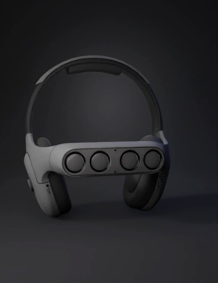
headset with sensors 3d model
Tags
gadget
lidar sensor
props
props realistic
props rendering
props rendering realistic
realistic
rendering
rendering realistic
Prompt
1. Overall Design Philosophy The primary goal is to create a 3D model that looks like a sleek, modern "gadget," not a medical device. The design should be minimalist, comfortable, and balanced. It integrates all components (LiDAR, mics, bone conduction, ESP32, battery) into a cohesive form factor. 2. Component-by-Component Modeling Guide Component 1: The Main Headband Purpose: The main chassis that connects all components. Blender Approach: Start with a Bézier Curve (Shift + A > Curve > Bézier). In Edit Mode, shape the curve to follow the path of a "band over the head," like a standard pair of headphones. In the Object Data Properties (green curve icon) for the curve, go to the Geometry tab. Increase the Bevel > Depth to give the curve thickness. Aesthetic (Knit Band): To get the "Apple knit band" look, you could apply a Displace modifier with a "Clouds" or "Noise" texture, or (for a more advanced approach) use a fabric texture map in the material. Placement: This is the central "spine" of the device. Component 2: The Front Sensor Bar (Visor) Purpose: Houses the 4x LiDAR sensors in a single, sleek module. Blender Approach: Start with a Cube (Shift + A > Mesh > Cube). Add a Subdivision Surface modifier to make it smooth and rounded. Add a Mirror modifier (on the X-axis) so you only have to model one side. In Edit Mode, shape the cube into a smooth, slightly curved "visor" or "bar" that attaches to the front of the headband. Sensor Ports: Create one small Cylinder. Duplicate it 3 times. Place these 4 cylinders where the LiDAR sensors will be (e.g., two forward, two angled to the sides). Select the main visor object, add a Boolean modifier, set it to Difference, and select the 4 cylinders as the Object. This will cut perfect holes for the sensors. Placement: Sits on the front of the headband, just above the user's eyebrows. Component 3: Side Modules (Bone Conduction & I/O) Purpose: Houses the bone conduction transducers, microphones, and panic button. Blender Approach: Start with another Cube + Subdivision Surface + Mirror modifier. Shape it into a smooth, ergonomic module that attaches to the ends of the headband. This part should be modeled to sit in front of the ear, on the cheekbone. Bone Conduction Pad: Create a flat, circular Cylinder and Boolean (Union) or Join it to the inner face of the module. This is the part that will make contact with the user. Mic Ports: Create 4 tiny Cylinder objects (2 on each side) and use the Boolean (Difference) modifier to create small perforations for the microphones. Panic Button: On one of the side modules, model a simple, tactile button (e.g., a small, extruded cylinder in a circular cutout). Placement: At the ends of the headband, resting on the user's cheekbones. Component 4: Rear Module (Counterbalance) Purpose: Houses the ESP32 and battery to balance the weight of the front sensors. Blender Approach: Start with another Cube + Subdivision Surface modifier. Shape it into a small, curved module that attaches to the back of the headband, at the base of the skull. Keep this part simple and low-profile. Placement: Sits on the back of the headband. 3. Materials & Texturing Headband: A dark, fabric-like material. Use a Noise Texture node connected to the Bump input of your Principled BSDF shader for a simple fabric feel. Sensor Bar & Side/Rear Modules: A matte or semi-gloss plastic. Set the Roughness on the Principled BSDF to around 0.7 (for matte) or 0.3 (for semi-gloss). Sensor Lenses: A dark, glossy "glass." Set Roughness to 0.0 and Transmission to 1.0 (or just make it a glossy black). Bone Conduction Pad: A soft-touch, rubbery material (high Roughness, maybe a dark grey).
Detailed Info
Related Models
Enter invite code
Enter invite code to get credits!