3D Workspace
Home
Assets
Affiliate Program
Sign up/Log in
?
Upgrade
DCC Bridge
Anonymous1765970573
12-18 04:21
Model Name
lab equipment 3d model
Tags
lab equipment
machine
machine realistic
machine rendering
machine rendering realistic
realistic
rendering
rendering realistic
vacuum chamber
vacuum pump
Prompt
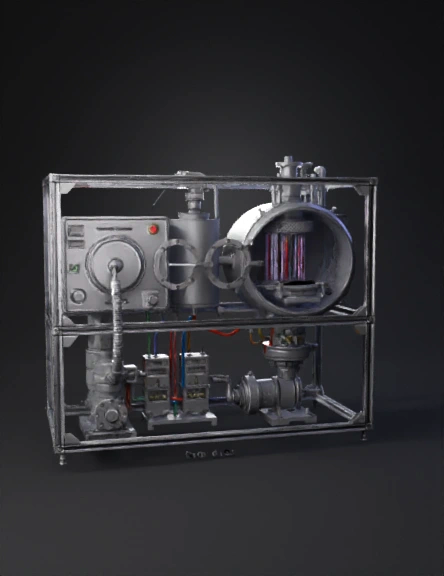
1. Overall Tool Structure (Outer to Inner) The etching system is a closed vacuum-based processing tool mounted on a rigid frame, typically connected to a sub-fab below for pumps and gas handling. Main internal sections: Load lock chamber Transfer chamber (robot) Process (etch) chamber Plasma generation system Gas delivery & exhaust system Wafer chuck (electrostatic chuck) RF power & control modules 2. Load Lock Chamber (Wafer Entry) Purpose: Isolate cleanroom air from vacuum environment. 3D elements to show: FOUP port at the front Load lock door Vacuum pump connection Pressure gauges Working: Wafer enters from FOUP Load lock door closes Chamber is pumped down from atmospheric pressure to vacuum Once pressure matches process chamber, wafer transfers inside 3. Transfer Chamber & Robot Arm Purpose: Move wafers without human contact. 3D elements: Central vacuum chamber Multi-axis robotic arm Wafer end-effector (blade) Gate valves to process chambers Working: Robot arm picks wafer from load lock Rotates and aligns wafer Inserts wafer into the etch chamber Entire movement occurs under vacuum 4. Etch Process Chamber (Core Section) This is the heart of the etching tool. 4.1 Chamber Body Cylindrical or rectangular metal chamber Inner walls often coated (Al₂O₃ / Y₂O₃) to reduce contamination 4.2 Wafer Chuck (Electrostatic Chuck – ESC) 3D elements: Flat circular chuck Embedded electrodes Helium backside cooling channels Working: Wafer is clamped electrostatically Helium gas improves heat transfer Chuck temperature tightly controlled (±1°C) 5. Plasma Generation System Used in Plasma Etching / Reactive Ion Etching (RIE). 5.1 Gas Injection (Top) 3D elements: Showerhead plate Gas inlet pipes (CF₄, SF₆, Cl₂, O₂, etc.) Working: Process gases flow uniformly into chamber Gas distribution ensures even etching 5.2 RF Power System 3D elements: RF generator Matching network RF electrode (top or bottom) Working: RF power ionizes gases → plasma Plasma contains ions, radicals, and electrons Bias voltage accelerates ions toward wafer 6. Etching Mechanism (Material Removal) Two mechanisms occur simultaneously: 6.1 Chemical Etching Reactive radicals chemically react with wafer material Forms volatile byproducts 6.2 Physical Etching (Ion Bombardment) Ions strike wafer surface vertically Enables anisotropic (vertical) etching Critical for fine patterns For 3D animation: Show glowing plasma Show ions moving downward Show material being removed layer by layer 7. Exhaust & Vacuum System 3D elements: Exhaust port at chamber bottom Throttle valve Turbo pump Dry vacuum pump (sub-fab) Working: Byproducts are continuously removed Pressure precisely controlled (mTorr range) Prevents redeposition of etched material 8. Endpoint Detection System Purpose: Stop etch at correct layer. 3D elements: Optical emission sensor Viewing window or fiber optic line Working: Monitors plasma light spectrum Detects material change Sends signal to stop process 9. Post-Etch Wafer Exit Steps: RF power turns off Plasma extinguishes Chamber purged Wafer unclamped Robot retrieves wafer Wafer returned to load lock Load lock vents to atmosphere 10. Sub-Fab (Below the Tool) For realistic 3D model, include: Vacuum pumps Gas cabinets Scrubbers RF power cabinets Cooling water lines
Detailed Info
Related Models
Enter invite code
Enter invite code to get credits!