3D Workspace
Home
Assets
Affiliate Program
Sign up/Log in
?
Upgrade
DCC Bridge
Anonymous1769426767
02-07 15:41
Model Name
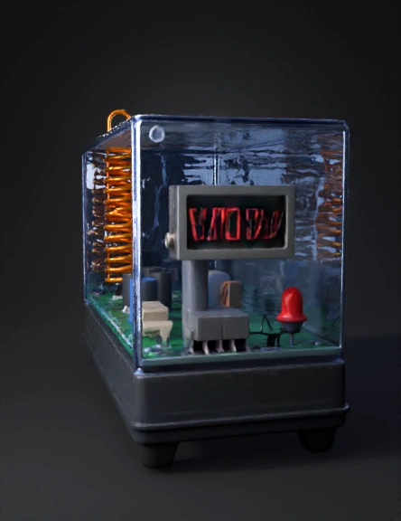
rf energy harvester 3d model
Tags
electromagnetic
electronics component
machine
machine realistic
machine rendering
machine rendering realistic
realistic
rendering
rendering realistic
Prompt
3D Model Description for Electromagnetic Energy Harvesting Device Main Structure: Create a rectangular electronic project case measuring 15cm x 10cm x 5cm with a transparent acrylic top cover. The base should be made of dark gray plastic material with rounded corners and small rubber feet at the bottom corners. Circuit Board: Inside the case, place a green PCB (printed circuit board) measuring 12cm x 8cm, mounted 1cm above the base using 4 small standoffs at the corners. The board should have visible copper traces connecting components. Electronic Components on Board: Antenna: A coiled copper wire antenna (golden/bronze color) rising vertically from the left side of the board, forming a helical coil shape - 10 turns, 5cm diameter, 8cm tall Diodes: 4 small black cylindrical components (3mm diameter, 6mm long) arranged in a row across the middle of the board, each with a silver stripe on one end Capacitors: 2 small yellow ceramic capacitors (disc-shaped, 5mm diameter) 3 cylindrical electrolytic capacitors (blue color, 8mm diameter, 12mm tall) with silver tops LED Indicator: One red LED (5mm diameter) positioned at the front right corner, slightly elevated Resistors: 2 small beige/tan cylindrical components with colored bands (2mm diameter, 6mm long) Connection wires: Thin red and black wires connecting components Display Panel: On the front face of the case, embed a small digital voltmeter display (LCD screen, 3cm x 1.5cm) showing "0.00V" in red digits with black background. Labels: On the top transparent cover, add etched or printed text: "RF ENERGY HARVESTER" in bold letters at the top "Electromagnetic Power Collection Device" in smaller text below Small warning symbol (⚡) near the antenna Color Scheme: Case base: Dark gray (#404040) PCB: Green (#2E7D32) Antenna coil: Copper/gold (#B87333) Transparent cover: Clear with slight blue tint LED: Bright red Capacitors: Blue with silver tops Diodes: Black with silver stripe Additional Details: Add 2 small ventilation slots on both sides of the case (1cm x 3cm) Include 4 mounting screw holes at the corners of the PCB (visible brass/gold) Small power indicator LED on the front panel (green, 3mm) Textured surface on the case base (matte finish) The antenna should have a clean, professional spiral shape with even spacing between coils Viewing Angle: Position the model at a 30-degree angle from the front-right corner to show both the transparent top (revealing internal components) and the front display panel.
Detailed Info
Related Models
Enter invite code
Enter invite code to get credits!