3D Workspace
Home
Assets
Affiliate Program
Sign up/Log in
?
Upgrade
DCC Bridge
3D Creation Made Simple
Text & Image to 3D Model in seconds
One-Click Texturing & Smart Detail Editing
Free Credits Monthly
Start Free
Anonymous1766664034
12-25 12:07
Model Name
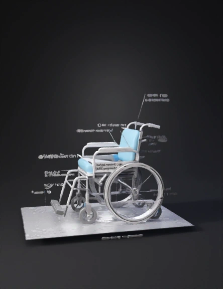
wheelchair 3d model
Tags
machine
rendering
realistic
Prompt
A. Side-View Wheelchair Diagram: How to Draw It (Step-by-Step) This is a functional schematic, not a CAD drawing. Keep lines simple and proportions realistic. Step 1: Draw the Ground Reference Draw a straight horizontal line. Label it: Ground reference plane. Step 2: Draw the Rear Wheel (Primary Wheel) Draw a large circle (~24-inch diameter). This is the rear propulsion wheel. Add a smaller concentric circle to represent the handrim. Label: Rear wheel (24 in) Handrim (rubber-coated aluminium) Step 3: Draw the Rear Axle Mark the axle at the centre of the rear wheel. Add a short horizontal adjustment slot to show adjustability. Label: Adjustable rear axle position Step 4: Draw the Front Caster Draw a smaller wheel forward of the rear wheel. Connect it to the frame with a simple fork. Label: Front caster (dual-bearing) Step 5: Draw the Frame Connect rear axle to front caster with a straight or gently angled line. Extend frame upward behind the rear wheel for backrest support. Label: Frame (Aluminium 6061-T6) Step 6: Draw the Seat and Backrest Draw the seat pan slightly angled backward. Draw the backrest reclined relative to vertical. Angles to show (important): Hip angle: 100–110° Backrest angle: 90–120° adjustable Label: Seat pan Backrest (reclinable) Step 7: Draw the Cushion (Conceptual) Slightly thicken the seat surface. Divide into three zones using dashed lines: Ischial support zone Thigh support zone Sacral relief zone Label: PU gel + memory foam cushion (pressure-relieving) Step 8: Draw the Footrest Assembly Draw footrest forward of the seat. Show telescoping by drawing a dashed extension. Label: Adjustable footrest (ABS polymer) Step 9: Draw the Brake Mechanism Draw a simple lever pressing against the rear wheel. Label: Mechanical parking brake Step 10: Draw the Anti-Tip Device Draw a small wheel behind the rear wheel near the ground. Label: Rear anti-tip caster Step 11: Mark the Centre of Gravity (Critical) Draw a dot 4–5 cm anterior to the rear axle. Draw a vertical dashed line from the dot to the ground. Label: Combined system centre of gravity (CoG) This is extremely important academically. B. What Your Final Diagram Should Contain (Checklist) Before submitting, confirm you have: ✔ Rear wheel (24 in) ✔ Handrim ✔ Adjustable axle ✔ Front caster ✔ Frame ✔ Seat and backrest ✔ Cushion zones ✔ Footrests ✔ Brake ✔ Anti-tip device ✔ Centre of gravity ✔ Hip and knee angles
Detailed Info
Related Models
Enter invite code
Enter invite code to get credits!