3D Workspace
Home
Assets
Affiliate Program
Sign up/Log in
?
Upgrade
DCC Bridge
Anonymous1770307377
02-05 16:16
Model Name
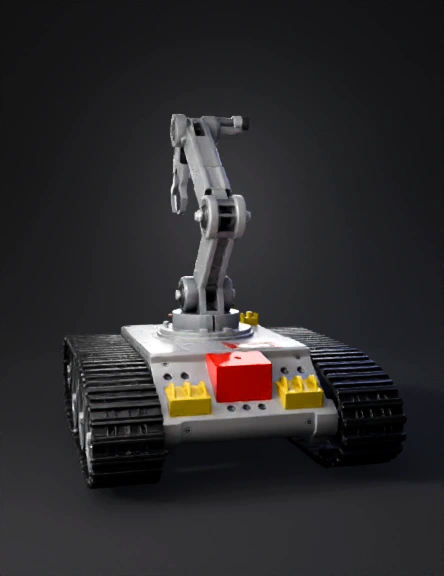
tank robot 3d model
Tags
realistic
rendering
rendering realistic
tank robot
vehicle
vehicle realistic
vehicle rendering
vehicle rendering realistic
Prompt
Act as a Fusion 360 mechanical design expert and robotics mentor. I want a COMPLETE, step-by-step Fusion 360 guide to design a TANK ROBOT WITH A ROBOTIC ARM from scratch. Do NOT skip any step. Assume I am a beginner. Design requirements: - Robot type: Tank robot with robotic arm - Drive system: Rubber tank wheels with continuous track (medium size) - Wheels: Circular wheels clearly visible - Motors (drive): BO motors (66 × 26 × 25 mm) - Motor position: Bottom-mounted (under the base plate) - Arm type: 4-DOF robotic arm (base rotation, shoulder, elbow, gripper) - Arm mounting position: Center-top of the base plate - Arm material: Plastic / aluminum - Base plate required - Battery holder required - Controller mount required (Arduino / Raspberry Pi + motor driver) - Proper use of COMPONENTS (not only bodies) - Capture Design History must be ON - Design must support full 360° rotation - Final model must be shareable using a Fusion 360 Public Link (online viewer) Robotic arm specifications: - Arm base rotation: 360° vertical axis - Shoulder link length: ~80 mm - Elbow link length: ~70 mm - Wrist / gripper mount included - Simple two-finger gripper - Servo-based joints (standard servo size: 40 × 20 × 40 mm) - Clear joint alignment for animation The guide must include: PART A – TANK ROBOT 1. Creating a new Fusion 360 design 2. Turning ON Capture Design History 3. Creating the base plate with exact dimensions 4. Converting bodies into components correctly 5. Designing BO motors with correct dimensions 6. Placing motors at the bottom (left & right) 7. Creating motor shafts 8. Designing tank drive wheels 9. Aligning wheels with motor shafts 10. Creating idler wheels 11. Patterning wheels for tank layout 12. Designing a simple tank track (belt) using sweep PART B – ROBOTIC ARM 13. Creating the robotic arm base (rotating pedestal) 14. Designing servo motor housings 15. Designing shoulder link 16. Designing elbow link 17. Designing wrist / gripper mount 18. Designing a two-finger gripper 19. Aligning joints using revolute joints 20. Ensuring arm motion clearance from tank body PART C – ELECTRONICS & MOUNTING 21. Designing battery holder 22. Designing controller mount with holes 23. Adding mounting holes to base plate 24. Cable routing space PART D – FINISHING 25. Applying fillets for smooth edges 26. Applying materials (rubber, metal, plastic) 27. Checking full 360° rotation (tank + arm) 28. Testing arm movement using joints 29. Generating a Fusion 360 Public Share Link 30. Optional export steps (STL / STEP) Rules: - Use clear numbered steps - Use simple beginner-friendly language - Mention exact Fusion 360 menu paths (example: Solid → Create Sketch) - Do NOT jump steps - Do NOT assume prior knowledge - Explain common beginner mistakes and how to avoid them Final output must read like a complete beginner-to-finish tutorial for a tank robot with a robotic arm.
Detailed Info
Related Models
Enter invite code
Enter invite code to get credits!