3D Workspace
Home
Assets
Affiliate Program
Sign up/Log in
?
Upgrade
DCC Bridge
Anonymous1760556444
10-16 07:40
Model Name
microfluidic biosensor 3d model
Tags
machine
machine realistic
machine rendering
machine rendering realistic
microfluidic
realistic
rendering
rendering realistic
Prompt
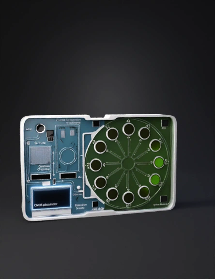
Goal: Design a compact, dual-compartment microfluidic biosensor device with realistic features for pathogen detection and antibiotic susceptibility testing of Klebsiella pneumoniae. --- 🔸 Overall Device Structure Create a rectangular base chip: 100 mm × 60 mm × 8 mm (approx.). Divide the chip into two main compartments: Compartment A (left): Detection of K. pneumoniae Compartment B (right): Antibiotic susceptibility testing Add a microfluidic channel between A and B for controlled fluid transfer. Include transparent surfaces (glass-like material) for visualization and embedded sensors. --- 🧪 Compartment A — Detection Module Inlet Port: Cylindrical opening (2–3 mm) for blood sample injection on the top left corner. Peristaltic Pump Line: Small embedded channel (0.5–1 mm) connecting inlet to separation unit. Plasma Separation Unit: Rectangular chamber with thin microporous membrane (0.45 µm) texture — place just after the inlet. Capture Chamber: Size: 15 mm × 10 mm × 2 mm Add bead mixing region (spherical or toroidal pocket) to simulate oscillating magnetic field zone. Magnetic Bead Zone: Indicate placement of magnetic field (e.g., rectangular base under chamber). Reporter Phage Injection Port: A tiny side inlet. Optical Detection Layer: Place a CMOS photodiode panel beneath this chamber — add emissive blue light in the scene to visualize NanoLuc luminescence (~460 nm). Micro-valve Outlet: Tiny channel leading to Compartment B. --- 💊 Compartment B — Antibiotic Susceptibility Testing (AST) Chamber Shape: Circular disk (diameter 40 mm, depth 2 mm). Central Inlet: From Compartment A channel. Radial Microchannels: Create 8–12 thin channels (0.5–1 mm wide) branching from center like a sunburst. Wells: Circular wells (3–4 mm diameter each) arranged around the perimeter. Embed a thin hydrogel layer inside each well to represent pre-loaded antibiotics. RBP Coating Layer: Slight color or texture difference to indicate surface coating. Optical Sensor Array: Small square panels beneath each well to represent CMOS photodiodes. Label Wells: (e.g., “A1”, “A2”, … “A12”) for different antibiotics. --- 🧭 Additional Design Details Use transparent glass material for fluidic parts and white/metallic base for structural support. Color-code compartments: Blue tint — Compartment A Green tint — Compartment B Add tiny arrows or flow indicators on channels for fluid movement direction. Include text labels: “Plasma Separation”, “Capture Chamber”, “Detection Sensor”, “AST Wells”, etc. Optional: Add luminescence effect in wells to represent signal intensity differences (susceptible vs resistant). --- ⚡ Suggested Blender Tools / Modifiers Boolean Modifier: for channels and wells. Array Modifier: to duplicate radial wells evenly. Curve + Bevel: for smooth microfluidic channels. Subdivision Surface + Solidify: for transparent top layer. Emission Shader: for luminescence simulation. Text Object: for labeling
Detailed Info
Related Models
Enter invite code
Enter invite code to get credits!