3D Workspace
Home
Assets
Affiliate Program
Sign up/Log in
?
Upgrade
DCC Bridge
Anonymous1776949738
04-27 12:55
Model Name
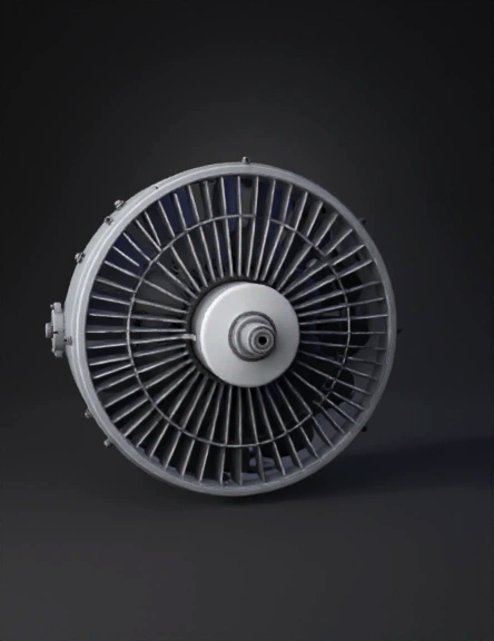
jet engine turbine 3d model
Tags
airfoil
compressor
jet engine turbine
machine
machine realistic
machine rendering
machine rendering realistic
realistic
rendering
rendering realistic
rotor blades
turbine
Prompt
Compressor: The axial-flow compressor section consists of the compressor rotor and the compressor casing. Within the compressor casing are the variable inlet guide vanes, the various stages of rotor and stator blading, and the exit guide vanes. In the compressor, air is confined to the space between the rotor and stator where it is compressed in stages by a series of alternate rotating (rotor) and stationary (stator) airfoil-shaped blades. The rotor blades supply the force needed to compress the air in each stage and the stator blades guide the air so that it enters the following rotor stage at the proper angle. The compressed air exits through the compressor discharge casing to the combustion chambers. Air is extracted from the compressor for turbine cooling, bearing sealing, and for pulsation control during startup. The compressor portion of the gas turbine rotor is an assembly of wheels, two stubshafts, each with an integral wheel, a speed ring, tie bolts, and the compressor rotor
Detailed Info
Related Models
Enter invite code
Enter invite code to get credits!