3D Workspace
Home
Assets
Affiliate Program
Creator Program
Sign up/Log in
View Plans
DCC Bridge
krishbhadja01210
01-29 09:36
Model Name
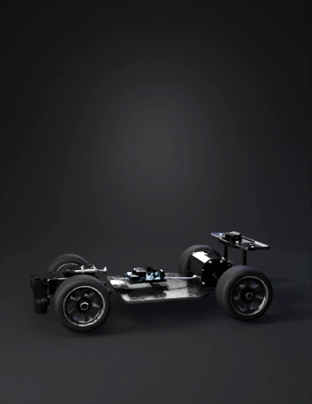
autonomous car prototype 3d model
Tags
autonomous
realistic
rendering
rendering realistic
vehicle
vehicle realistic
vehicle rendering
vehicle rendering realistic
Prompt
Create a clean, professional, engineering-style 3D CAD model of a toy-sized autonomous self-driving car prototype (not a full vehicle). The design must look world-class / world-best, premium, minimal, robust, and manufacturable—like a top-tier robotics prototype. Output high-resolution renders on a plain white background with soft studio lighting and subtle shadow. No logos, no text labels on the model, no watermark, no people, no environment. REQUIRED OUTPUT VIEWS: 3D assembled CAD view (isometric 45°) 3D exploded view (all parts separated slightly, aligned clearly, easy to understand) Orthographic views: Top, Side, Front Dimension lines in millimeters for overall length, width, height, wheelbase, track width, and ground clearance GLOBAL DESIGN RULES: Use clean fillets/chamfers, symmetric layout, perfect weight balance, professional brackets/standoffs, and neat cable routing channels (or omit wires). Use matte neutral CAD materials (dark gray, light gray, aluminum), sharp edges, realistic screws (M3), no random extra parts. Where “typical module sizes” are given, treat them as reference dimensions with small tolerance (±2 mm) while keeping the design realistic and buildable. ======================== A) CHASSIS + MECHANICAL DIMENSIONS (MUST FOLLOW) Chassis plate: Length: 250 mm Width: 150 mm Thickness: 3 mm Corner radius: 12 mm Mounting hole pattern: M3 holes (Ø3.2 mm) at 10 mm inset from each corner + electronics holes described below Ground clearance: 10 mm Wheelbase (front axle center to rear axle center): 170 mm Track width (wheel center left-to-right): 120 mm Wheels (4 pcs): Rear wheels: Ø60 mm, width 18 mm, hub bore Ø4 mm Front wheels: Ø50 mm, width 16 mm, hub bore Ø4 mm Tire style: smooth rubber-like profile, no text Axles: Rear axle: Ø4 mm rod, length 130 mm Front axle steering knuckles: realistic RC-style knuckles with kingpin axis; keep compact Steering (RC-style): Steering servo body: 23 mm (L) × 12.5 mm (W) × 24 mm (H) Servo horn: Ø18 mm disc / arm length 20 mm Steering linkage rods: Ø2 mm, length ~45 mm each (use realistic ball joints) Steering arm/bracket: 35×20×3 mm plate (with fillets) Drive motor + gearbox (rear): Motor can: Ø27 mm × 50 mm length Gearbox housing: 60 mm (L) × 35 mm (W) × 30 mm (H) Motor mount bracket: 70×40×3 mm with slots, M3 holes ======================== B) ELECTRONICS MODULES (SHOW AS REALISTIC 3D BLOCKS WITH DIMENSIONS) Arduino Uno (mounted on standoffs): Board: 68.6 mm (L) × 53.4 mm (W) × 1.6 mm (thickness) Max component height above board: 14 mm Standoffs: Ø6 mm × 10 mm height, M3 screws Motor Driver (choose ONE version, but show correct size): Option 1 TB6612FNG module: Board: 32 mm × 21 mm × 1.6 mm Max height: 10 mm Option 2 L298N module: Board: 43 mm × 43 mm × 1.6 mm Heatsink height: 25 mm (total module height approx 30 mm) Battery pack (2×18650 holder, 2S): Holder block: 78 mm (L) × 40 mm (W) × 22 mm (H) Add small protection/BMS block (optional): 35×20×8 mm Place battery low-left for stability Power switch + fuse (clean industrial look): Rocker switch: 21 mm (L) × 15 mm (W) × 18 mm (H) Inline fuse holder block: 28×10×10 mm (optional) ======================== C) SENSORS (AUTONOMY) WITH DIMENSIONS Ultrasonic sensor (HC-SR04 style) front bumper: PCB: 45 mm × 20 mm × 1.6 mm Dual transducers: Ø16 mm × 12 mm depth (x2) Mount bracket plate: 55×25×3 mm with fillets (Alternative ToF sensor: 25×20×8 mm — show only if you prefer ToF) IR Line Sensor Array (5–8 sensors) under front: Array board: 70 mm (L) × 20 mm (W) × 1.6 mm Sensor height from ground: 6–10 mm Mounting bracket: 80×25×3 mm IMU module (MPU6050 size) centered: Board: 20 mm × 15 mm × 6 mm height Wheel encoders (recommended, rear axle): Encoder disc: Ø25 mm × 1 mm thickness Sensor bracket: 20×12×2 mm Mount near rear axle on both sides (or one side) ======================== D) OPTIONAL COMPUTE + VISION (SHOW AS DASHED / ALTERNATE CONFIG) Raspberry Pi (optional, mounted above Arduino on standoffs): Option Pi 4 size: Board: 85 mm × 56 mm × 1.6 mm Max height: 18 mm Option Pi Zero 2 W size: Board: 65 mm × 30 mm × 1.6 mm Max height: 12 mm Camera module (optional) on front-top bracket: Camera PCB: 25 mm × 24 mm × 6 mm height Adjustable tilt bracket: 35×20×3 mm + hinge pin Ø3 mm ======================== E) ELECTRONICS MOUNT HOLES (ON CHASSIS) Arduino mount hole grid: 50 mm × 40 mm rectangle (M3 holes Ø3.2 mm) Motor driver mount: 25 mm × 15 mm (TB6612) OR 35 mm × 35 mm (L298N) Battery mount slots: 70 mm × 25 mm spacing, elongated slots 6×3.5 mm Sensor mounts: provide M3 holes and neat brackets ======================== F) FINAL RENDER REQUIREMENTS Exploded view must clearly show: chassis, wheels/axles, steering servo + linkage, motor+gearbox, Arduino, motor driver, battery pack, power switch, ultrasonic/ToF, IR array, IMU, encoders, optional Pi + camera. Use realistic screws (M3), standoffs, and clean mounting hardware. No messy wiring (either omit wiring or show minimal clean routed cable paths in channels). Must look like a world-best industrial design: premium, minimal, robust, perfectly aligned, and build-ready. NEGATIVE CONSTRAINTS: No text labels on the model, no brand logos, no watermark, no people, no scenery, no cartoon look, no unrealistic proportions, no low detail, no blur.
Detailed Info
Related Models
Enter invite code
Enter invite code to get credits!