3D Workspace
Home
Assets
Affiliate Program
Creator Program
Sign up/Log in
View Plans
DCC Bridge
elad.lifshin
01-21 08:37
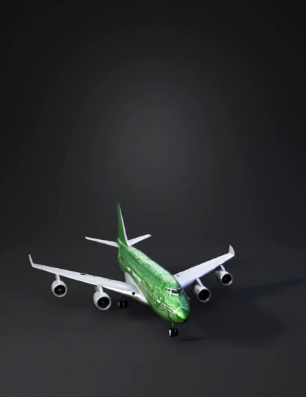
Model Name
boeing 747 3d model
Tags
3d printing
3d printing realistic
747
realistic
vehicle
vehicle 3d printing
vehicle 3d printing realistic
vehicle realistic
Prompt
Create a fully closed, manufacturing‑ready 3D model of a Boeing 747 for SLA printing. Global requirements (critical): • Single continuous watertight manifold. No separate parts, no zero‑thickness faces, no non‑manifold edges, no self‑intersections. • All geometry must be printable in single‑material SLA; do not rely on thin decals or separate shells. • Outer shell is part of the aircraft’s form (not an internal offset only). Keep thickness consistent. Overall look & scale: • Realistic Boeing 747 proportions: fuselage, cockpit nose, wings with proper sweep/dihedral, vertical & horizontal stabilizers, four engine nacelles, landing‑gear bay locations. • Target overall fuselage length ≈ <set length, e.g., 300 mm>. Maintain true proportions. • Export as watertight OBJ/GLB with UVs. Surface style & textures (entire aircraft = PCB theme): • Apply a full‑body PCB motif over the entire aircraft (fuselage, wings, tail, nacelles): green solder‑mask look with white silkscreen lines and occasional copper‑trace patterns. • Convert key PCB traces/silkscreen into shallow embossed/recessed geometry so details survive sanding and painting: – Trace line width ≥ 0.8 mm; relief height/depth 0.4–0.6 mm. • Randomly sprinkle a few very small, low‑profile “electronic component” cubes (black IC packages) on selected surfaces (for example on the wings and upper fuselage): – Each cube with softened edges (fillet 0.5–1.0 mm) and blended base to avoid stress risers. – Keep minimum feature thickness ≥ 1.0 mm and avoid fragile standoffs; components must merge smoothly into the skin. Colors (for visualization/paint guide only): • Global theme: PCB green with white silkscreen. Optional metallic gray accents for engines. Pearl‑white highlight is NOT required; the PCB theme covers the entire aircraft. Detailing with SLA safety: • Windows and doors must be embossed/recessed panels (NO through‑holes) to preserve the outer skin. • Panel lines/markings: width ≥ 0.8 mm, depth/height ≥ 0.6 mm. • Engine fan details: simplify to ribs thickness ≥ 1.0 mm. Wall thickness & robustness (brittle resin‑safe): • Outer skin (fuselage/wings/tail/nacelles): uniform wall thickness ≥ 3.0 mm following the outer curvature. • Trailing edges (wings/tail): safe edge thickness ≥ 1.2–1.5 mm (no knife edges). • Any rod/strut‑like features ≥ 2.0–2.5 mm diameter. • Apply generous fillets/rounds at all junctions (r ≥ 0.8–1.5 mm) and blend every added element into the primary body. Stand‑ready hole (future stand, not part of this model): • On the underside of the fuselage (centered below the CG, between landing‑gear bay areas) create a rectangular through‑slot to accept a future stand tongue. • Default slot size: 24 mm (L) × 12 mm (W) × 18 mm (H); internal corner fillets 0.5–0.8 mm; 0.5–1.0 mm external chamfer at the opening. • Maintain ≥ 3.0 mm material around all sides of the slot. Do not include the stand model. Print‑oriented constraints (SLA): • Orient features to minimize heavy supports; keep local overhangs ≥ 45° where feasible. Where not possible, integrate short internal ribs that are removable after printing. • Avoid sealed cavities that trap resin. If any hollow volumes are required, add at least two hidden drain/vent holes Ø ≥ 2.5–3.0 mm on the underside. • Target tolerances: general ±0.3–0.5% (min ±0.3 mm) on decorative features. • No separate floating parts; no paper‑thin details; no perforated window rows. Deliverables: • A single, closed, manifold model suitable for SLA slicing; OBJ/GLB with UVs for the PCB motif; all silhouette‑affecting details as real geometry per dimensions above. ``
Detailed Info
Related Models
Enter invite code
Enter invite code to get credits!