3D Workspace
Home
Assets
Affiliate Program
Sign up/Log in
?
Upgrade
DCC Bridge
Anonymous1763155759
12-10 16:42
Model Name
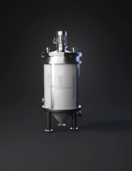
stainless steel reactor 3d model
Tags
bioreactor
machine
machine realistic
machine rendering
machine rendering realistic
realistic
rendering
rendering realistic
stainless steel reactor
Prompt
“Create a highly detailed and technically accurate 3D model of a 10-liter bioreactor according to the following engineering specifications. All dimensions, proportions, and mechanical features MUST match the description. The model must be suitable for industrial visualization and scientific use. 1. Main Vessel Geometry – Internal volume: 10 L – Internal diameter D = 20 cm – Working liquid height H = 31.8 cm (H/D = 1.59) – Cylindrical stainless-steel body (316L) or borosilicate glass – Wall thickness: 3–5 mm – Bottom: light conical shape (20°–30°) – Top lid: removable, bolted flange, multiple ports 2. Cooling Jacket – External annular cooling jacket – Gap between tank and jacket: 20–40 mm – Jacket inlet at the bottom, outlet at the top – External diameter with jacket: 24–26 cm 3. Internal Mixing System 🔹 Agitator Shaft – Material: stainless steel – Diameter: 1 cm – Runs vertically through the top with a mechanical seal – Motor + coupling must be mounted on top 4. Impeller (CRITICAL SECTION – MUST BE EXACT) 🔸 Type: 6-blade Rushton turbine You MUST generate a true Rushton disc turbine, NOT a propeller, NOT an axial fan, NOT pitched blades. ✔ Geometry requirements (STRICT): – Central flat circular disc thickness 3–5 mm – Disc diameter Di = 6.7 cm (≈ 1/3 of tank diameter) – Six flat vertical blades welded perpendicularly around the disc – Blade height: 1–1.5 cm – Blade thickness: 3–5 mm ✔ Blade orientation (CRITICAL – DO NOT CHANGE): – Blades must be perfectly vertical (90°), flat, and perpendicular to the disc – Blades must NOT be tilted upward or downward – Blades must NOT be angled like an axial propeller – This is a classical RUSHTON turbine, NOT an axial-flow impeller. ✔ Impeller position – The center of the impeller MUST be placed 10.6 cm above the tank bottom (exactly 1/3 of the vessel height) – MUST NOT be attached to the bottom – MUST NOT float too high ❗ HARD RULES – If the blades are angled, curved, twisted, aerodynamic, or shaped like a fan → REGENERATE – If the blades point forward or look like a propeller → REGENERATE – If the disc is missing → REGENERATE 5. Baffles (Internal Stabilizers) – Four (4) vertical baffles – Height: from 2 cm above base to 2 cm below lid – Width: 2 cm (≈ D/10) – Thickness: 0.5–1 cm – Clearance from tank wall: 3–5 mm 6. Sparger System – Type: annular ring or perforated tube – Placed 2–5 cm above tank bottom – Tube diameter: 0.5–1 cm – Perforations: 8–16 holes, 1–2 mm 7. Ports and Sensors On top lid: – Inoculation port: 1/4’’ – Feed port: 1/4’’–3/8’’ – Center port for agitator shaft with seal – Gas outlet / condenser: 1/4’’ On tank wall: – pH probe entrance at 40–50% of total height – DO probe near same height – Temperature probe near impeller elevation – Sampling port at 30–40% of height – Harvest valve at bottom or lower lateral region 8. Structural Support – Three or four tubular legs – Clearance under tank: 8–12 cm – Flanged connections with bolts or sanitary clamps 9. Modeling Requirements – Watertight geometry – Sharp industrial edges (no smoothing) – Realistic stainless-steel PBR – Clean topology suitable for animation – Maintain all mechanical details: valves, clamps, nozzles, disc, blades, motor housing 10. Summary of Vertical Layout – Top lid with motor, shaft seal, and ports – Sensor zone (pH, DO, temperature) – Rushton impeller placed exactly 10.6 cm above the bottom – Sparger 2–5 cm above bottom – Conical bottom with drain Generate the complete 3D model exactly as described, preserving all dimensions and ensuring the Rushton impeller is modeled with correct industrial geometry (flat vertical blades on a disc, not angled).”
Detailed Info
Related Models
Enter invite code
Enter invite code to get credits!