3D Workspace
Home
Assets
Affiliate Program
Sign up/Log in
?
Upgrade
DCC Bridge
Anonymous1765399380
12-10 22:05
Model Name
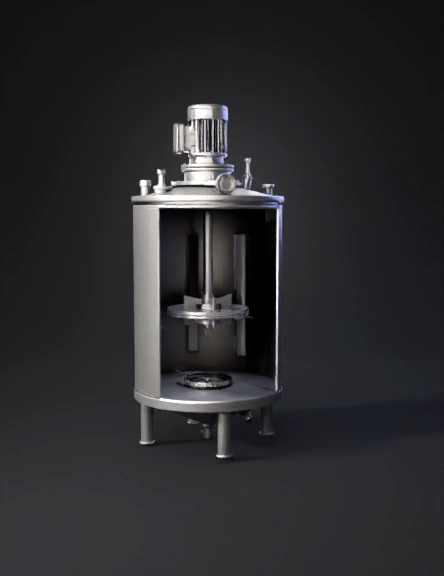
industrial mixer 3d model
Tags
bioreactor
industrial mixer
industrial mixing tank
machine
machine realistic
machine rendering
machine rendering realistic
realistic
rendering
rendering realistic
Prompt
Create a highly detailed and technically accurate 3D model of a 10-liter stirred bioreactor. The model must combine two features: (1) a visible internal structure with correctly placed impeller, and (2) external components such as motor, ports, and support legs. 1. Tank and Materials Main cylindrical tank: borosilicate glass, but only the front half is transparent so the internal components are fully visible. Back half of the cylinder: opaque stainless steel 316L. Top lid and bottom base: metallic stainless steel 316L (not transparent). Cooling jacket: stainless steel around the upper opaque back half. 2. Internal Impeller (CRITICAL REQUIREMENT) ⚠️ This is the most important part; do NOT skip or simplify. Inside the tank, include one 6-blade Rushton impeller, mounted on a central shaft. The impeller must be completely visible through the transparent front. Orientation: Horizontal flat disk Blades vertical, evenly spaced around the disk Correct Rushton geometry (not angled like a fan, not pitched) Position: The impeller must be placed at exactly one-third of the tank height, approximately 10.6 cm above the tank bottom. NOT near the base. NOT touching the bottom. Shaft: stainless steel, goes straight up to the mechanical seal. 3. Top Motor Assembly Include a top-mounted electric motor + gearbox, aligned with the shaft. Add mechanical seal on the lid. Add radial ports, nozzles, sensors, and clamps on the lid. 4. Internal Details 4 vertical baffles, stainless steel, 2 cm wide, suspended with 3–5 mm gap from the wall. Sparger ring 2–5 cm above the base with perforations. Internal probes mounted on the side wall: pH probe at 40–50% height DO probe at 40–50% height Temperature probe near impeller level Sampling port at 30–40% height. Drain/harvest valve at the bottom. 5. Bottom Section & Support Legs Base: stainless steel dish or shallow cone. Add 3 or 4 metallic tubular support legs, as in the reference model. Clearance under tank: 8–12 cm. Keep drain valve accessible below. 6. Visualization Requirements Maintain a clean vertical cutaway transparency on the front half of the cylinder so the impeller, shaft, sparger, and baffles are visible. Back half remains metallic to keep structural realism. All metallic parts: stainless steel PBR. Topology should be clean, symmetrical, and watertight. 7. Absolutely Required The Rushton impeller MUST be visible through the transparent front. The impeller MUST be centered and positioned at 1/3 height, not at the bottom. Do not remove the motor or the support legs. Do not remove ports, valves, sensors, or baffles. Add a wide vertical cutaway opening on the front half of the tank, extending from just below the top lid down to the bottom section, so that the internal components (central shaft, Rushton impeller positioned at 1/3 height, baffles, sparger, and sensors) are clearly visible from the outside. The cutaway must be: Wide, covering at least 30–40% of the tank’s circumference. Vertical, centered on the front. Clean and smooth, not jagged. It must NOT remove or distort any internal parts. Do NOT modify any of the following: Motor, gearbox, top lid or ports. Support legs. Internal shaft, baffles, sensors, valves, sparger, or impeller position. Materials (glass front half + stainless-steel back half). Keep everything exactly as it is; only add the large cutaway opening so the impeller becomes fully visible. There should be no columns, towers, supports, or vertical elements near the blades or around the impeller. The blades must be completely free, without interference, suspended only by the central shaft.
Detailed Info
Related Models
Enter invite code
Enter invite code to get credits!