3D Workspace
Home
Assets
Affiliate Program
Creator Program
Sign up/Log in
View Plans
DCC Bridge
klaapikla
01-18 10:01
Model Name
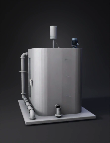
water-oil separation 3d model
Tags
fluid
machine
machine realistic
machine simulation
machine simulation realistic
realistic
simulation
simulation realistic
Prompt
Create a highly realistic, engineering-accurate 3D model of an above-ground rectangular water–oil separation and circulation system. The model must represent a real-world constructible system, not a conceptual or artistic visualization. All dimensions must be physically plausible and consistent with fluid volumes. Use metric units only (meters, millimeters, liters). The model must be suitable for mechanical review, section cuts, and interactive rotation. ================================================== OVERALL SYSTEM LAYOUT ================================================== - Total system width (left to right): 3.0 meters - Tanks are aligned horizontally and share common outer walls where applicable - Structure is placed on a flat concrete base slab - All tanks are rectangular prism shapes - Tank walls have uniform thickness - All pipes are rigid industrial pipes (PVC-U or HDPE depending on diameter) - Pipes penetrate tank walls using proper flanged or bulkhead fittings ================================================== MATERIAL SPECIFICATIONS ================================================== TANK STRUCTURE: - Material: Reinforced concrete or HDPE industrial tank - Wall thickness: 100 mm - Bottom slab thickness: 150 mm - Internal surfaces are smooth and waterproofed PIPES: - Material: - ≤20 mm: PVC-U (Schedule 40 equivalent) - ≥25 mm: HDPE or PVC pressure pipe - All pipes are cylindrical, hollow, with correct wall thickness ================================================== TANK 1 – RAW WATER INTAKE TANK ================================================== Function: Receives raw, partially contaminated water from an external source. Internal volume capacity: 600 liters Operational fill volume per cycle: 500 liters Internal dimensions: - Length (X-axis): 1.0 m - Width (Y-axis): 1.0 m - Effective water height: 0.6 m External dimensions (including walls): - Length: 1.2 m - Width: 1.2 m - Height: 0.8 m Internal components: - Float switch mounted on side wall - Electric solenoid valve mounted inline on inlet pipe -------------------------------------------------- PIPE #1 – RAW WATER INLET -------------------------------------------------- - Internal diameter: 25 mm - External diameter: 32 mm - Pipe wall thickness: 3.5 mm - Pipe length: 0.6 m (from source to Tank 1 wall) - Pipe enters horizontally from the left side wall at 0.3 m height ================================================== PIPE #2 – TRANSFER FROM TANK 1 TO TANK 2 ================================================== - Internal diameter: 25 mm - External diameter: 32 mm - Length: 1.0 m - Includes: - Inline centrifugal pump - Electric shutoff valve - Pipe exits Tank 1 at bottom section - Pipe enters Tank 2 at mid-height Purpose: Transfers 500 liters per cycle. Operates exactly four cycles to deliver 2000 liters total. ================================================== TANK 2 – MAIN MIXING AND SEPARATION TANK ================================================== Function: Primary tank for water storage, oil injection, mixing, separation, and clean water discharge. Maximum capacity: 2500 liters Operational volume: - Water: 2000 liters - Oil added: 20 liters - Total liquid volume: 2020 liters Internal dimensions: - Length: 1.0 m - Width: 1.0 m - Height: 2.5 m External dimensions: - Length: 1.2 m - Width: 1.2 m - Height: 2.7 m Internal components: - Level sensor (top-mounted) - Volume sensor - Mixer assembly (Component #7) -------------------------------------------------- MIXER #7 – INTERNAL AGITATOR -------------------------------------------------- - Vertical shaft-mounted mixer - Shaft diameter: 40 mm - Shaft length: 2.0 m - Three mixing blades - Blade diameter: 300 mm - Mounted centrally on tank floor - Electric motor mounted above tank roof Purpose: Mixes water and oil temporarily. Stops completely to allow gravity-based phase separation. ================================================== TANK 3 – OIL STORAGE TANK ================================================== Function: Stores reusable oil for injection into Tank 2. Operational oil volume per cycle: 20 liters Internal dimensions: - Length: 0.6 m - Width: 0.6 m - Height: 0.6 m External dimensions: - Length: 0.8 m - Width: 0.8 m - Height: 0.8 m ================================================== PIPE #3 – OIL INJECTION PIPE ================================================== - Internal diameter: 16 mm - External diameter: 22 mm - Wall thickness: 3 mm - Length: 0.8 m - Includes: - Small precision pump - Flow sensor Pipe enters Tank 2 from upper side wall and discharges oil near liquid surface. ================================================== PIPE #4 – OIL OVERFLOW SEPARATION PIPE ================================================== Function: Extracts only the separated oil layer after mixing stops. - Internal diameter: 20 mm - External diameter: 26 mm - Wall thickness: 3 mm - Length: 1.2 m - Installed diagonally downward from left (higher) to right (lower) - Inlet height corresponds to the 2000-liter water level Flow behavior: Oil flows by gravity. Flow stops automatically when liquid level drops below pipe inlet. ================================================== TANK 4 – OIL FILTRATION TANK ================================================== Function: Receives extracted oil and removes contaminants. Operational volume: 20 liters Internal dimensions: - Length: 0.5 m - Width: 0.5 m - Height: 2.5 m External dimensions: - Length: 0.7 m - Width: 0.7 m - Height: 2.7 m Internal components: - Bottom-mounted filtration cartridge - Oil outlet port above filter -------------------------------------------------- PIPE #5 – OIL RECIRCULATION PIPE -------------------------------------------------- - Internal diameter: 25 mm - External diameter: 32 mm - Length: 1.0 m - Includes pump - Returns filtered oil back to Tank 3 for reuse ================================================== PIPE #6 – CLEAN WATER DISCHARGE PIPE ================================================== Function: Final discharge of clean water after oil separation. - Internal diameter: 32 mm - External diameter: 40 mm - Wall thickness: 4 mm - Length: 2.0 m - Located at bottom of Tank 2 - Uses gravity flow only (no pump) ================================================== MODEL REQUIREMENTS ================================================== - Show correct pipe routing and penetration through walls - All tanks must have visible wall thickness - Internal components must be visible or semi-transparent - Model must support: - Rotation - Cross-section views - Web-based embedding (Three.js / Sketchfab) - No artistic exaggeration - All proportions must reflect real-world construction logic
Detailed Info
Related Models
Enter invite code
Enter invite code to get credits!
 klaapikla


 klaapikla