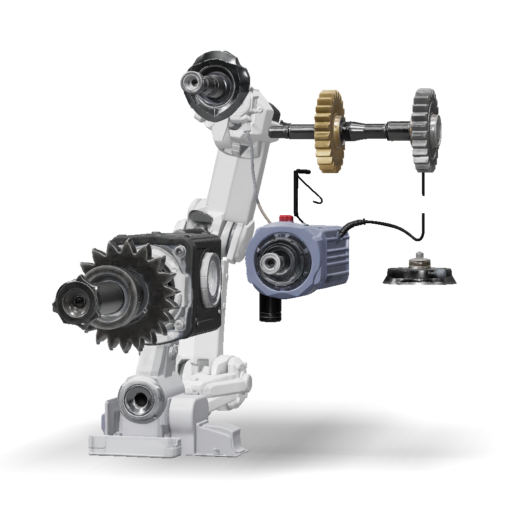
robotic arm joint 3d model
Create a mechanically realistic 3D CAD robotic-arm joint using TWO MG996/MG996R servos driving ONE dedicated metal output shaft. Do NOT connect servo horns directly. Use synchronized spur gears: Servo A → gear train → output; Servo B → matching gear train → output, with slight compliance/floating adjustment to prevent servo fighting. Use two bearings to support the output shaft so arm loads bypass servo shafts. Create a compact, rigid, modular FDM-printable housing with servo mounts, bearing seats, gear cavities, access cover, ribs, alignment features, fasteners, cable openings, and mechanical stops. Show assembled, exploded, and sectional views revealing torque and bearing load paths. Use realistic gear module, teeth, ratio, face width, center distances, shaft diameters, clearances, and dimensions in mm. Use metal for shaft, bearings, gears, and spline adapters; PETG/ABS/ASA/nylon for housing. Include BOM, materials, FDM orientation, assembly sequence, torque/load analysis, realist
2K·PBR·v3.1-20260211


