3D Workspace
Home
Assets
Affiliate Program
Creator Program
Sign up/Log in
View Plans
DCC Bridge
guadalupegerardo1
11-23 19:39
Model Name
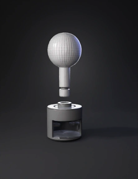
ball and rod 3d model
Tags
joystick
props
props realistic
props rendering
props rendering realistic
realistic
rendering
rendering realistic
xbox
Prompt
“Create a precise, CAD-style, 3D-printable two-piece arcade joystick adapter designed to fit on top of an Xbox One analog stick. The model must be mechanical, watertight, symmetrical and optimized for real-world use. Do NOT add textures, logos, decorations or curved engravings. Avoid floating pieces. All geometry must be clean and manufacturable. PART A — ARCADE JOYSTICK (Upper Piece) Classic Japanese arcade ball-top. Ball diameter: 25 mm, perfect sphere. Shaft: 6 mm diameter, 28 mm length, perfectly cylindrical. Bottom connection peg: 4 mm diameter × 12 mm length, centered. Add a 0.5 mm chamfer at the bottom of the peg for easy insertion. 4 mm from the peg, add a 1.5 mm wide circumferential groove to interface with internal travel stoppers. This entire joystick must be one single, clean, solid mesh. PART B — ADAPTER CAP (Lower Piece) Designed to fit over an Xbox One analog stick. Main cavity Internal cylindrical cavity: 12.0 mm inner diameter 10.0 mm depth 3° internal taper for friction fit. Fully open bottom. Outer diameter: 18 mm, wall thickness: 3 mm. Anti-button-press safety features Add an asymmetric lower recess/cutout on the side facing the controller buttons. Recess: 2.5 mm deep, 3 mm of radial clearance, preventing contact with nearby buttons when the cap tilts. Peg interface & pivot Centered top hole: 4.2 mm diameter (0.2 mm clearance for peg). Surround the hole with a 2 mm tall internal bushing that acts as the pivot point for the joystick shaft. Built-in movement limiters (travel stops) Inside the cap, add two radial internal stoppers, spaced 180° apart. These stoppers must contact the joystick’s shaft groove and limit tilt to approximately ±12° (≈3–4 mm lateral top movement). The stops must engage before the external skirt can touch the controller or buttons. Protective skirt / clearance flange Add a 3 mm lower skirt around the bottom edge with a slight undercut, ensuring the cap never touches controller buttons during tilt. Manufacturing requirements Both parts must be separate solid watertight meshes, clean and printable in STL. No non-manifold edges, no self-intersection, no floating components. Designed for 3D printing (PLA or TPU) with 0.2 mm tolerances on fits.
Detailed Info
Related Models
Enter invite code
Enter invite code to get credits!