3D Workspace
Home
Assets
Affiliate Program
Creator Program
Sign up/Log in
View Plans
DCC Bridge
Anonymous1772787608
03-06 10:27
Model Name
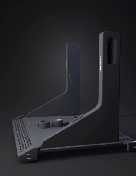
rack mount bracket 3d model
Tags
3d printing
3d printing realistic
props
props 3d printing
props 3d printing realistic
props realistic
rack mount
realistic
Prompt
Create a precision-engineered 3D model of a 10-inch mini rack 1U mount bracket designed to hold two UniFi power adapters. The mount must be a single-piece rack accessory with two angled cradle trays extending from a front rack plate. The design should resemble a professional network rack accessory, with clean mechanical geometry similar to parts designed in Fusion 360, SolidWorks, or Onshape. ⸻ Rack Standard The mount must follow the 10-inch mini rack standard. Front rack plate height: 44.45 mm (1U) The complete assembly including the adapters must not exceed the 1U height limit. No element may extend above this height. ⸻ Adapters to Support Adapter 1 UniFi 210W AC Adapter Approx dimensions: 190 mm length 86 mm width 26 mm height Weight about 1.2 kg. ⸻ Adapter 2 Gateway Fiber AC adapter Approx envelope: 210 mm length 110 mm width 30 mm height. ⸻ Provide realistic installation clearance: • 2–3 mm side clearance • 2 mm front clearance • 2 mm rear clearance Adapters must drop vertically into the cradle trays from the top and remain stable. ⸻ Rear Cable Clearance Adapters must not sit directly against the rack plate. Create a rear cable clearance gap between the rack plate and the adapter cradle structure so the power cables can exit without sharp bending. This spacing must allow natural cable routing behind the adapters. ⸻ Rear Spacer Pipes Add four cylindrical spacer pipes between the rack plate and the cradle structure. These spacers must: • maintain the rear cable clearance gap • structurally support the cradle assembly • resemble the cylindrical spacers visible in the reference bracket They should be evenly spaced and symmetrical. ⸻ Cable Routing Notches Each cradle must include a cable pass-through notch in the front border wall. Requirements: • allow cable to exit the adapter and route backward • smooth rounded edges • no sharp corners The cable must be able to pass through the notch and route through the rear clearance space. ⸻ Rack Mounting Holes The rack mounting holes must be horizontal oval / slotted holes, not round holes. Purpose: • allow mounting tolerance • allow alignment adjustment during installation Slots must be symmetrical and clean. ⸻ Cradle Borders The cradle borders should be tapered or pyramid-like, similar to professional rack brackets. These borders must: • prevent adapters from sliding forward • support the adapters • allow easy insertion from the top Maintain sufficient internal clearance. ⸻ Tray Angle The cradle trays must be angled upward relative to the rack plate. Target angle: 35 to 40 degrees This improves cable routing and adapter stability. ⸻ Structural Reinforcement The mount must be strong enough to support the heavy power adapters. Add: • triangular gussets between tray arms and rack plate • reinforcement ribs under cradle trays Recommended thickness: rack plate 3.5–4 mm tray floor 4 mm reinforcement ribs 3 mm Avoid thin fragile structures. ⸻ Ventilation Add diamond-shaped ventilation cutouts in the cradle floors. Requirements: • symmetrical pattern • allow airflow under adapters • maintain structural strength ⸻ Cable Safety All cable routing areas must include rounded or chamfered edges to prevent cable damage. Avoid sharp edges. ⸻ FDM Printing Optimization The mount must be optimized for FDM 3D printing. Requirements: • printable as one solid object • printable flat on the build plate • avoid overhangs greater than 45° • avoid thin unsupported features • include fillets at structural transitions The model should print reliably on standard desktop FDM printers. ⸻ CAD-Style Geometry Requirements Generate the model with clean mechanical CAD-style geometry. Requirements: • planar surfaces • crisp edges • symmetric construction • consistent wall thickness • manifold geometry • no intersecting surfaces • no organic sculpted shapes The model should resemble a parametric CAD design, not a soft mesh. ⸻ Geometry Forcing Trick (Important) Construct the model using simple parametric primitives combined with symmetry constraints. Use: • rectangular plates • cylindrical spacers • triangular gussets • planar support trays All major components should be aligned to orthogonal axes and mirrored where possible. Surfaces must be flat planes joined by fillets or chamfers, not curved organic shapes. Topology should resemble extruded mechanical features typical of CAD software. ⸻ Industrial Style The final design should look like a professional UniFi rack accessory: • minimal industrial design • balanced structural cutouts • lightweight but strong • practical engineering appearance Avoid decorative shapes. ⸻ Final Output Generate a single printable rack mount bracket including: • two adapter cradle trays • rear cable clearance zone • four cylindrical spacer pipes • slotted rack mounting holes • tapered cradle borders • cable routing notches • diamond ventilation cutouts • structural reinforcement ribs • full compliance with the 1U height limit
Detailed Info
Related Models
Enter invite code
Enter invite code to get credits!