3D Workspace
Home
Assets
Affiliate Program
Creator Program
Sign up/Log in
View Plans
DCC Bridge
swasti.d.sahoo
12-06 16:54
Model Name
prosthetic hand 3d model
Tags
machine
machine realistic
machine rendering
machine rendering realistic
prosthetic hand
realistic
rendering
rendering realistic
Prompt
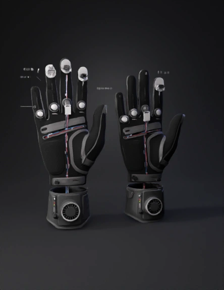
Create a professional, engineering-grade 3D model of the “Symbiome Glove” — a wearable biomedical prototype glove intended as a competition-ready, serviceable, multi-part assembly. Work in millimetres (mm) and produce both printable meshes (STL/OBJ/GLB) and a CAD-editable STEP for rigid inserts. Output named parts and clearly separated subassemblies. Produce a watertight manifold mesh for printable parts and solids for the rigid inserts. Include high-resolution renders (front, back, palm close-up, exploded, cross-section) and an 8–12 second turntable MP4 animation showing assembled + exploded assembly. Follow the exact engineering brief below. General design goals Target: comfortable ergonomic fit for an average adult right hand (male/female adjustable) — palm width ~80–95 mm, palm length ~95–110 mm, finger lengths: index 75 mm, middle 85 mm, ring 80 mm, pinky 65 mm, thumb 60 mm (design parametric so scale can be adjusted). Two part system: FLEX_SKIN (outer flexible shell — TPU-like) and RIGID_INSERTS (PLA/ABS-like snap-in housings). Provide separable bodies: GLV_SKIN_TOP, GLV_SKIN_PALM, GLV_FINGER_MODULES, INSERTS_DORSAL, INSERTS_WRIST, WIRE_COVERS. Human factors: model anatomically correct finger taper and curvature, thumb at ~35° opposition, relaxed hand posture with 10° natural flex at MCP joints. Provide visible flex-relief channels on dorsal side across MCP/PIP/DIP (length 6–12 mm each) and 0.6–1.0 mm chamfered flex radii. Ensure internal clearance for a 2.5 mm fabric/foam liner and optional 2 mm silicone pad. Materials & thickness (explicit) FLEX_SKIN: shell thickness 1.2–1.8 mm (TPU-like), micro-texture on palm for grip (0.3 mm pattern), perforated vent holes in flex zones 0.8 mm diameter grid. RIGID_INSERTS: wall thickness 2.5–3.2 mm, all edges filleted 0.6–1.0 mm. Add 0.8–1.2 mm fillets at internal corners. Snap-fit tolerances: 0.20 mm clearance on all press-fits. Minimum printable feature: 0.8 mm. Sensor housings and exact dimensions (each must include mounting bosses / sealing grooves / wiring channel) Index fingertip PPG / HRV optical pocket (label: PPG_HOUSING_IDX) External circular recess diameter 10.0 mm, depth 3.0 mm. Internal lens pocket diameter 6.0 mm, depth 3.0 mm with O-ring groove (1.5 mm wide x 0.8 mm deep). Cable exit channel: 1.8 × 1.8 mm rectangular channel, radius turn ≥ 5.0 mm, routes to dorsal wire trunk. Snap feature: 2 × 1.8 mm press-clips for translucent cover. Middle & ring finger GSR pads (label: GSR_PAD_MID; GSR_PAD_RING) Palmar flush pad recess 12.0 mm diameter × 0.6 mm deep, isolation trench around pad 0.8 mm deep. Rear mounting post boss for 2-pin snap or M2 screw (boss outer dia 5.0 mm, inner 3.0 mm). Internal channel 1.8 × 1.8 mm to dorsal trunk. Mark pads ‘GSR+’ and ‘GSR–’. Pinky pH / sweat proxy port (label: PH_PORT_PINKY) Micro-reservoir 4.0 mm dia × 1.5 mm deep with snap cap (3.0 mm thread depth). 0.6 mm microfluid groove leading to reservoir for demo sample strip. Include printed clip docking point for disposable strip (3 × 1.5 mm slot). Back-of-hand IMU housing (label: IMU_HOUSING_DORSAL) Recess 28 × 18 × 6 mm, four M2.5 bosses, foam cushion recess 2 mm under housing. Vent holes: 2 mm diameter × 2 channels. Include keyed orientation pin hole 3.0 mm dia × 4.0 mm depth. Environmental sensor vent (label: ENV_PORT_WRIST) Radial wrist slotted vent 18 × 6 mm with internal baffle channels; route a short channel to wrist module (1.8 mm). Wrist microcontroller & battery bay (label: MCU_HOUSING_WRIST; BATTERY_BAY) PCB footprint seat 60 × 30 × 2.5 mm with four M2.5 bosses (screw holes: countersink for M2.5). Battery pocket 35 × 20 × 6 mm (3.7V LiPo 350 mAh). Removable hatch with rubber gasket groove 1.5 mm wide; hatch latch snap; USB-C cutout 6.6 × 2.4 mm; JST-SH 4-pin external breakout recess. Include external antenna aperture. Wiring channels and cable management Continuous dorsal wire trunk 1.8–2.0 mm width × 1.2–1.6 mm depth running from fingertips → wrist, with smooth 5–8 mm radius bends. Snap-on covers every 30–40 mm (press-fit rails). Include 2.5 mm anchor clip slots and strain relief slots at each sensor exit and at the MCU housing. Provide routing for separated power/data pairs (label channels POWER, SIGNAL). Provide external demonstration tether port on wrist sized for 2-pin/4-pin JST. Mechanical & assembly details Snap-fit sockets for sensor modules (0.5 mm draft). Keyed connector slots to avoid incorrect orientation. Boss geometry for M2.5 screws: boss OD 5.0 mm, inner dia 3.0 mm, height 3.5 mm. Include removable service hatch underside of wrist; countersunk screw holes present. Alignment dowel pins: 3.0 mm dia × 4.0 mm length at each assembly seam. Add embossed part names on rigid inserts and arrows showing alignment. Haptics & UI Palm pocket for coin vibration motor diameter 12.0 mm, depth 3.5 mm with flexible membrane. Radial wrist tactile pushbutton 6 mm dia × 2 mm travel with LED window 2.5 × 4 mm; three dorsal status LED windows (R/G/A) each 2.5 mm dia with diffuser slot. Add thin LED diffuser groove along dorsal spine (2.5 × 1.0 mm). Place a 6 mm recessed tactile icon area for tap feedback. Comfort, sealing & ventilation Silicone gasket grooves around wrist hatch & sensor capsules (1.5 mm face width). Micro ventilation holes (0.8 mm) across flex zones. Palm micro-textured grip (hex pattern 0.3 mm depth). Foam pad recess pockets sized 2 mm thick. Print & manufacturability instructions Split model into printable subassemblies: FINGER_MODULES (5 parts), PALM_SHELL, DORSAL_INSERTS, WRIST_MODULE, WIRE_COVERS. Design dovetail alignment features for assembly. Provide print orientation suggestions: fingers printed vertically, wrist printed flat. Minimum feature size 0.8 mm. Fillet radii min 0.5 mm. Tolerances for snap fits +0.20 mm. Provide chamfers on mating faces for easy assembly. Naming, outputs & documentation Output these exact filenames: symbiome_glove_v1.stl, symbiome_glove_inserts.step, symbiome_glove_wire_covers.stl, symbiome_exploded_render_front.png, symbiome_exploded_render_back.png, symbiome_exploded_animation.mp4. Parts must be named internally exactly: GLV_SKIN_TOP, GLV_SKIN_PALM, GLV_FINGER_MODULE_INDEX, GLV_FINGER_MODULE_MIDDLE, GLV_FINGER_MODULE_RING, GLV_FINGER_MODULE_PINKY, PPG_HOUSING_IDX, GSR_PAD_MID, GSR_PAD_RING, PH_PORT_PINKY, IMU_HOUSING_DORSAL, ENV_PORT_WRIST, MCU_HOUSING_WRIST, BATTERY_BAY, WIRE_CHANNELS_DORSAL, HAPTIC_POCKET, WATER_GASKETS. Include a one-page BOM: recommended materials (TPU Shore 85A for skin, PLA/ABS for rigid inserts), recommended battery spec (3.7V LiPo 350 mAh), recommended sensor footprints (MAX30102 optical pad: 6 mm lens pocket; GSR pad: 12 mm circular pad), connector type JST-SH 4-pin, and PCB footprint 60×30 mm with M2.5 holes. Rendering & deliverables Produce high-res renders (4K PNG): front, back, palm close-up, exploded assembly, cross-section showing internal wiring. Produce 8–12 sec MP4 turntable animation showing assembled glove rotating and exploded assembly. Provide STEP for rigid inserts and STL for flexible skin parts. Provide tolerance notes (+/-0.2 mm critical) and assembly instructions PDF. Design intent summary Make the model production-grade: ergonomic, serviceable, clearly labeled, and visually striking — matte black flexible skin with charcoal grey rigid inserts and translucent LED diffusers. Ensure internal wiring channels are continuous, sensor housings are serviceable and sealed, and the wrist module supports future PCB/Bluetooth integration. Output both printable and CAD parts exactly as named for immediate use in Onshape/Fusion360. End.
Detailed Info
Related Models
Enter invite code
Enter invite code to get credits!