3D Workspace
Home
Assets
Affiliate Program
Sign up/Log in
?
Upgrade
DCC Bridge
Anonymous1770633951
02-09 12:49
Model Name
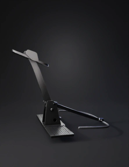
brake pedal assembly 3d model
Tags
machine
rendering
realistic
Prompt
Create a realistic 3D mechanical model of a brake pedal assembly for a small cart or light vehicle. The brake pedal consists of a vertical pedal arm with a rectangular pedal plate at the top for the driver’s foot. The pedal plate should have multiple round grip holes and a small side guard panel on one side to prevent the foot from slipping sideways. The pedal arm is mounted on a pivot located near the lower portion of the assembly and rotates around this pivot during braking. Behind the lower section of the pedal arm, place a long hinge lever micro switch (roller lever style) that acts as the brake over-travel safety switch. The micro switch must be mounted rigidly to the fixed base structure, not to the pedal arm itself. The pedal arm should normally press against its normal braking stop and must not touch the micro switch during normal braking operation. The long hinge lever micro switch is positioned directly behind the pedal arm so that only when the pedal travels beyond its normal braking range, due to loss of braking pressure or mechanical failure, the pedal arm continues moving and presses the long hinge lever, activating the switch and representing immediate system shutdown. The micro switch replaces the pressure actuator in this design and is the component that reacts to excessive pedal travel. The pedal assembly must allow pedal position adjustment for driver ergonomics, and when the pedal position is adjusted, the relative distance between the pedal arm and the micro switch must remain constant, meaning the switch is mounted to the same adjustable base or reference structure as the pedal pivot or pedal stop. Include two simplified hydraulic pressure pipes routed near the lower part of the pedal assembly to indicate brake system connections, shown only as basic tubes without detailed fittings. Use a clean industrial mechanical style with realistic proportions, neutral metal materials, and present the model in a clear side view or slight isometric view so the relationship between the pedal arm, pivot, and long hinge lever micro switch is easy to understand.
Detailed Info
Related Models
Enter invite code
Enter invite code to get credits!