3D Workspace
Home
Assets
Affiliate Program
Creator Program
Sign up/Log in
View Plans
DCC Bridge
Anonymous1772559697
03-09 20:44
Model Name
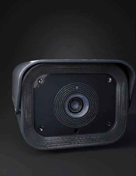
security camera 3d model
Tags
3d printing
3d printing realistic
props
props 3d printing
props 3d printing realistic
props realistic
realistic
security camera
Prompt
Create an image Objective: Design a precise, printable cover/housing for a Blink Outdoor security camera (latest model as of 2026) that mounts flush to a flat campervan surface using two built-in side M6 holes (lugless design). The cover must fully protect the camera while ensuring no obstruction to: 143° diagonal FOV (updated spec for Outdoor 4 / 2K+ models; older 3rd Gen was 110°) Microphone (2 directional mics, bottom-centered) PIR motion sensors (location varies by gen – dual PIR on newer models, positioned to avoid blockage) IR night vision illuminator Target Model: Blink Outdoor 4 (current flagship as of 2026) Exact dimensions: 70 mm (W) × 70 mm (H) × 41 mm (D) (Confirm your physical camera; if older 3rd Gen, it's 71 × 71 × 34 mm – use 71 × 71 × 41 mm cavity for universal slight clearance) Weight (with batteries): ~141–142 g FOV: 143° diagonal (critical – bezel must clear full cone; older models listed 110°, but use 143° for safety) Key front features (from official diagrams): Lens centered or slightly offset (top corner in some views for V4) Microphone: Bottom center (small holes/grid) PIR motion sensor(s): Above lens or integrated (dual on newer; ensure open path, no bezel overhang) IR emitter: Around lens Optional blue LED light nearby Material & Print Specs: Recommended filament: UV-stable ASA (outdoor weatherproof, UV-resistant; matches original spec) General tolerances: ±0.5 mm Critical interior cavity tolerance: ±0.1 mm (for snug fit without rattle) Print orientation: Back face (mating surface) down; tree supports for front bevel overhangs Other: 4–5 walls/perimeters, 25–40% gyroid infill, fillets on edges for strength/aesthetics Overall Geometry (from your provided drawings): Front orthogonal view: Octagonal/faceted profile Height: 140 mm Top width: 120 mm Bottom span: 110 mm (sides taper inward) Two circular M6 mounting holes (Ø6.4–6.5 mm for clearance) on sides, positioned per isometric (approx mid-height, symmetric) Isometric views: Beveled edges, flush-fit mating profile on back for campervan surface Interior cavity: Square pocket exactly matching camera body (70 × 70 mm or 71 × 71 mm) Depth: Camera depth (41 mm) + 3–5 mm front wall thickness + mounting/seating allowance → suggest total cover depth 44–48 mm (TBD/adjustable) Front bezel/window: Wide and shallow bevel/chamfer (Detail A style) Must flare outward to clear full FOV cone (143° diagonal) – no vignette or cutoff Shallow depth to maintain function Open bottom path for microphone/PIR (Detail B) – verify no obstruction with physical camera position Back: Flat seating plane for flush mount; slight inset/lip optional for better camera seating Mounting: Two side M6 screw paths (horizontal, through sides into campervan surface) Critical Design Notes (Non-Negotiable): Bezel must not obstruct the 143° FOV cone – visually wide/shallow; test cone clearance in CAD Microphone: Clear, unobstructed opening at bottom PIR sensor: Full clearance (no bezel lip blocking detection zone) – position verified against actual camera Flush-fit geometric profile for campervan surface mating No lugs – mounting via integrated side holes only Design for easy camera insertion/removal from back Optional: Slight fillets (0.5–1 mm) on outer edges; drain holes if needed for condensation Deliverables Requested: Editable source file: Fusion 360 (.f3d), FreeCAD, Onshape, or STEP/IGES Exported STL (high resolution, manifold/watertight) 3D render images (front, isometric, section view showing clearances) Optional: 2–3 variants (e.g., different depths or slight bezel adjustments) References Attached/Provided: Your two FRONT ORTHOGONAL VIEW images (140 mm H, 120 mm top, 110 mm bottom, faceted outline) Design specification sheet text (full original notes on tolerances, clearances, FOV, mic/PIR) Official Blink diagrams (for sensor placement): Older 3rd Gen front callout (PIR above lens, mic bottom, 110° FOV) Newer Outdoor 4 / V4 indicators (lens offset, dual PIR, mic bottom) Photos showing lens/mic/PIR on actual cameras (use for verification)
Detailed Info
Related Models
Enter invite code
Enter invite code to get credits!