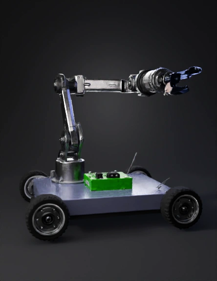
robotic arm 3d model
Design a detailed 3D CAD model of a 3-DOF mobile robotic manipulator within an overall bounding box of 400 mm × 400 mm × 600 mm. BASE CHASSIS: Rectangular aluminum base plate Size 380 mm × 360 mm × 3 mm Four 100 mm diameter wheels Wheel coordinates: (-140,150,0), (140,150,0), (-140,-150,0), (140,-150,0) Install four 12V geared motors aligned with wheels. BATTERY: 12V LiFePO4 battery centered at (0,0,30) Include mounting bracket. ELECTRONICS DECK: Aluminum plate 2 mm thick at height 60 mm Supported by M3 standoffs STM32 BOARD: Mount at (0,-120,60) MOTOR DRIVERS: Two BTS7960 modules Positions (-90,-40,55) and (90,-40,55) POWER SYSTEM: Fuse holder at (0,-20,40) Power bus bar near fuse XL4016 converter at (-40,-100,60) LM2596 converter at (40,-100,60) Capacitor bank at (0,-80,60) ARM BASE: Reinforced pedestal thickness 5 mm Mounted at (0,70,80) SHOULDER JOINT: High torque servo at (0,70,100) Include U-bracket and shaft support using 608ZZ bearing UPPER ARM: Aluminum link length 150 mm Use 8 mm steel sha
4K·PBR·v3.1-20260211


