3D Workspace
Home
Assets
Affiliate Program
Sign up/Log in
?
Upgrade
DCC Bridge
Anonymous1759512867
10-30 08:44
Model Name
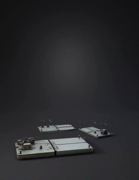
foam board hinge 3d model
Tags
machine
machine realistic
machine rendering
machine rendering realistic
prototyping
realistic
rendering
rendering realistic
Prompt
Design a highly accurate and visually exhaustive 3D engineering model that demonstrates a functional automated hinge mechanism connecting two lightweight rectangular foam boards for beginner engineering or STEM prototyping purposes. Each foam board should measure exactly 70 centimeters in length and 40 centimeters in width, shown with a uniform white or pale grey closed cell foam surface, with slightly rounded corners and subtle surface texture to indicate realistic foam material. The foam boards must be oriented along their longest sides so they share a contiguous edge, with this edge serving as the primary axis of rotation, replicating the behavior of a typical door or lid. The hinge mechanism should be depicted in two alternate configurations relevant for foam: first, using three evenly-spaced small cabinet-style butt hinges of polished stainless steel or high-strength polymer; second, using a single continuous piano hinge, also stainless steel or reinforced polymer, extending the full 70 cm length. The hinges need to be secured to both boards along the edge, with the butt hinges placed precisely: one at 7 centimeters from the left end, one at 35 centimeters (center), and one at 63 centimeters from the left end. Hinges should include visible mounting hardware, such as mini bolts, screws, or adhesive pads. The model should detail how the hinge leaves are affixed to foam boards without compromising structural stability, such as by reinforcing strips or creative mounting brackets suitable for a lightweight substrate. On the fixed foam board (base), showcase a compact servo motor, such as an SG90 micro servo or MG90S with metal gear, installed two centimeters away from the left edge, parallel to the hinge axis. Illustrate the servo motor with all visible features: a blue or black plastic body, metallic output shaft, and three colored wires (red for power, brown for ground, yellow/orange for signal). The motor should mount securely, possibly using a small 3D-printed bracket, adhesive pad, or lightweight clamp, appropriate for foam mounting. The servo arm should be extended perpendicularly, connected via a thin metal linkage or direct plastic arm to the underside of the rotating foam board. Emphasize the articulation—the mechanism must allow full 0 to 180-degree rotation without binding or excessive stress on the hinge or foam material. Integrate a compact microcontroller module to drive the servo, such as an Arduino Uno, Nano, or ESP32 board, with visible USB port, pins, and a simple wiring harness connected to the motor. Include a control interface, either a tactile push button mounted near the base foam board or an IR sensor positioned for touchless activation, shown with a miniature PCB or housing. Illustrate the control logic: pressing the button or activating the sensor sends a signal to the microcontroller, which then commands the servo to rotate the foam board from fully closed (0 degrees) to fully open (180 degrees), then reverse if pressed again. Depict both static and dynamic perspectives: present the foam boards in the fully closed state, perfectly parallel and flush, and in the fully open state, forming an exact 180-degree angle, with the hinges and actuator operating smoothly and without visible interference. Optionally, feature a sequence showing intermediate angles (45, 90, 135 degrees) to visualize mechanical range. Label every significant component with technical tags—foam board, hinge, servo motor, linkage, microcontroller, control button/sensor, mounting strips—so users can follow the construction and assembly. To enhance engineering clarity, create an exploded view showing component separation: highlight precise locations of hinge mounting, servo attachment, wiring runs, and reinforcement options. Add overlays with dimension arrows (centimeters), specifying the distance between hinges, servo placement, and board thickness. For added realism, use shadow and ambient occlusion to accentuate relief and part separation. Focus specifically on beginner-friendly choices, DIY-scale fabrication, and maximum cost-effectiveness, suggesting materials and assembly methods suitable for students or hobby innovators in India or similar environments. Exclude extraneous elements: do not model unrelated electronics, unnecessary landscape, excessive decorative features, or anything outside the foam-board, hinge, and actuator system. The scene should remain minimalist, well-lit, and visually pleasing, balancing technical rigor with clarity. If desired, include small stoppers, lips, or foam pads on the board edges to prevent over-rotation or damaging contact during movement. Finalize the 3D model with rendering intent suitable for simulation or animation: geometry should feature clean topology for hinges, boards, and moving assemblies, moderate polygon count for smooth operation, and high-resolution textures for foam and metal or plastic hinges. Ensure all movable parts (servo, hinge leaves, foam boards) are easily rigged for articulated animation. The delivered model should be appropriate for use in engineering visualization, educational demonstration, prototyping, product concept pitching, and DIY documentation. This prompt should produce a robust, polished, and highly specific 3D representation of an automated foam board hinge project, fulfilling all requirements for beginner engineering visualization and practical demonstration in an educational or prototyping context.
Detailed Info
Related Models
Enter invite code
Enter invite code to get credits!