3D Workspace
Home
Assets
Affiliate Program
Creator Program
Sign up/Log in
View Plans
DCC Bridge
einsteinsvjj
01-23 16:19
Model Name
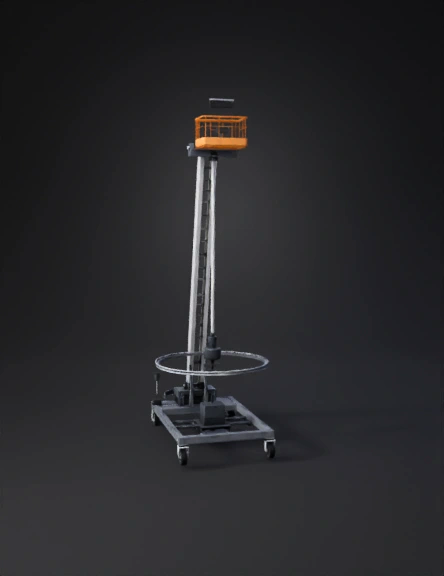
mobile cantilever ladder 3d model
Tags
cantilever
machine
machine realistic
machine rendering
machine rendering realistic
mobile
realistic
rendering
rendering realistic
Prompt
Design a mobile cantilever ladder system with an AI-assisted dynamic counterbalancing mechanism. The system consists of a vertical ladder mast with a cantilever working platform at the top, mounted on a rectangular wheeled base (rollers, not fixed to ground). The base houses a dual-degree-of-freedom movable counterweight system that dynamically shifts the system’s center of gravity to counter the overturning moment generated by an operator and carried load on the cantilever platform. Key requirements: Overall Structure Vertical ladder mast (height up to 7 m) Cantilever platform at the top with guard rails Rigid connection between mast and base frame Mobile base with four industrial caster wheels Base Frame Rectangular steel frame Low center of gravity Internal volume allocated for counterweight motion Fixed Ballast Central fixed ballast mass (≈ 60–80 kg) Mounted rigidly at the center of the base Movable Counterweight System (Primary Focus) Movable counterweight mass (≈ 150–220 kg) Mounted on a semi-circular rail beneath the ladder mast Rail radius between 1.0–1.5 m Rail spans 180° opposite to cantilever direction Dual-DOF Motion Angular motion: counterweight carriage rotates along the semi-circular rail Radial motion: counterweight slides inwards and outwards on a linear guide mounted on the rotating carriage Actuation Rotary actuator or servo motor with gearbox for arc motion Linear actuator (ball screw) for radial motion Both actuators mounted inside the base frame Sensors (Represented as Components) Load cells under ladder mast base Load cell under counterweight carriage Absolute rotary encoder for arc position Linear encoder for radial position IMU module mounted on ladder mast Safety & Realism Counterweight motion remains entirely inside base footprint No external ground-reaction actuators Actuators shown as self-locking (power-off safe) Visualization Exploded view showing counterweight mechanism Section view showing CG shift concept Clean industrial aesthetic (not conceptual art) The CAD model should clearly communicate mechanical feasibility, force paths, and dynamic counterbalancing logic, suitable for an engineering design review or final-year project submission.
Detailed Info
Related Models
Enter invite code
Enter invite code to get credits!