3D Workspace
Home
Assets
Affiliate Program
Creator Program
Sign up/Log in
View Plans
DCC Bridge
satya867srj
03-28 19:55
Model Name
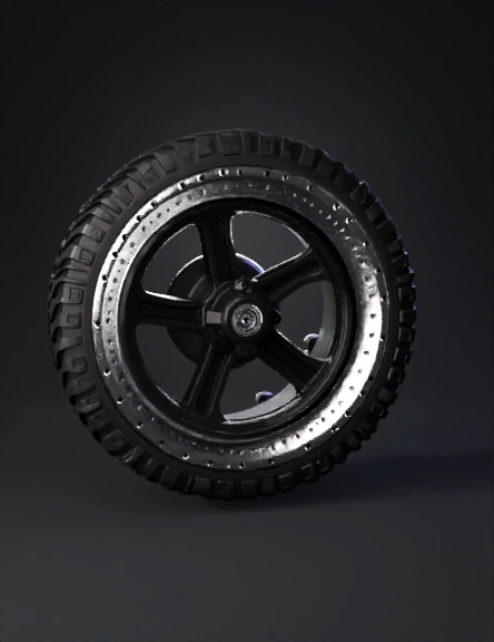
tire wheel 3d model
Tags
3d printing
3d printing realistic
realistic
tire wheel
vehicle
vehicle 3d printing
vehicle 3d printing realistic
vehicle realistic
Prompt
Design a parametric 3D CAD model of a planetary rover wheel for Project ARON (Autonomous Rover for Operational Navigation), a ground-based extraterrestrial mobility testbed. The wheel is a two-material FDM-printable assembly consisting of a structural core and a separate traction layer. All geometry must be manufacturable on a standard FDM 3D printer with a 0.4 mm nozzle and 0.2 mm layer height. Overall dimensions: Outer diameter: 120 mm. Total width: 60 mm. Hub bore diameter: 8 mm. Overall wall thickness of rim: 2.5 mm. Structural core — PETG-CF: Material annotation: PETG-CF (carbon fibre reinforced PETG). 8 radial I-beam spokes equally spaced at 45° intervals. Each spoke runs from the central hub to the inner rim surface. I-beam cross-section per spoke: flange width 6 mm, web height 8 mm, flange thickness 1.5 mm, web thickness 1.5 mm. Spoke length from hub outer edge to rim inner surface: approximately 42 mm. Hub: cylindrical, outer diameter 24 mm, bore 8 mm, width matching wheel width of 60 mm, with 4 M3 bolt holes at 16 mm bolt circle diameter for shaft collar attachment. Rim: hollow cylindrical shell, outer diameter 120 mm, inner diameter 115 mm (2.5 mm wall), width 60 mm. All spoke-to-rim and spoke-to-hub junctions must have a fillet radius of 2 mm minimum to reduce stress concentration at joints. 8 rectangular snap-fit slots on the outer rim surface, each 6.5 mm wide, 4.5 mm tall, 2 mm deep, positioned at 45° intervals for TPU sleeve attachment. Traction layer — TPU 95A: Material annotation: TPU 95A flexible filament. Cylindrical sleeve fitting over the outer surface of the PETG-CF rim. Outer diameter: 130 mm. Inner diameter: 120 mm (10 mm tread thickness). Width: 60 mm matching rim width. Traction pattern: 35 degree chevron grousers. Grouser profile: trapezoidal cross-section, base width 4 mm, tip width 2 mm, height 3 mm above tread surface. Grouser spacing: 12 mm centre to centre along the tread circumference. Chevron arms meet at the wheel centreline forming a V-shape pointing in the direction of forward rotation. Morse code surface feature: on the outer tread surface, emboss the text "ARON" encoded in Morse code as a raised surface pattern running continuously around the full circumference. Morse code sequence: .- .-. --- -. Encode each symbol as follows: dot = raised circular bump, diameter 3 mm, height 1 mm above tread surface. Dash = raised rectangular bar, length 7 mm, width 3 mm, height 1 mm above tread surface. Gap between symbols within a letter: 2 mm. Gap between letters: 5 mm. The full ARON sequence in symbols: A · − R · − · O − − − N − · Place the Morse code band as a single continuous horizontal strip running around the full circumference of the tread sleeve, centred at the wheel midline between the two chevron grouser arms. The band height reserved for the Morse code pattern is 10 mm, centred at the wheel width midpoint (30 mm from either edge). The pattern must not overlap with any grouser feature. One full ARON sequence is approximately 95–100 mm long — calculate the number of full repetitions that fit within the outer circumference of 408 mm (π × 130 mm) with minimum 10 mm spacing between repetitions, targeting 4 evenly spaced repetitions. All Morse code raised features must be printable without support in the upright print orientation. Sleeve attachment: 8 equally spaced snap-fit tabs on the inner surface of the sleeve, each tab 6 mm wide, 4 mm tall, 1.5 mm thick, engaging into the matching slots on the outer rim surface. The interface must allow the TPU sleeve to be press-fitted onto the rim and removed without tools for tread replacement. Assembly interface: The two components — PETG-CF structural core and TPU 95A traction sleeve — are separate bodies. The sleeve press-fits over the rim via the 8 snap-fit tab and slot pairs. No adhesive required. Concentricity maintained by the interference fit between sleeve inner diameter (120 mm) and rim outer diameter (120 mm). Print orientation guidance (embed as model annotation): Structural core: print with wheel axis horizontal so spoke I-beams are parallel to print layers — primary load path in X-Y plane. Minimum wall thickness for PETG-CF: 1.2 mm — all features comply. TPU sleeve: print upright with tread surface facing up — chevron grousers and Morse code features print without support in this orientation. Output required: Two separate component files. Component 1: PETG-CF structural core. Component 2: TPU 95A traction sleeve. Export formats: STEP and STL for each component. File names: ARON_wheel_core_PETG-CF.step, ARON_wheel_core_PETG-CF.stl, ARON_wheel_tread_TPU95A.step, ARON_wheel_tread_TPU95A.stl. If the tool supports parametric modelling, expose the following as editable parameters: outer diameter, spoke count, grouser height, grouser angle, Morse code bump height, and tread width.
Detailed Info
Related Models
Enter invite code
Enter invite code to get credits!