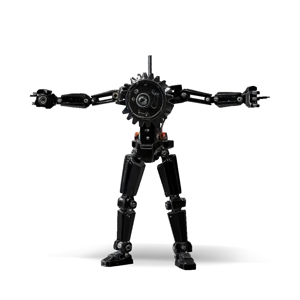
humanoid robot 3d model
Design an end effector (the gripping “fingers”) that mounts to the provided gear linkage using the 2× M3 screws + 2× M3 nuts. The two gear linkages open/close, so your parts must turn that motion into a practical grasping function. Assessment breakdown Functionality & Practicality — 20% Printability / Support Removal — 20% Easy to Assemble — 10% Demonstrating 3D Printing Technology — 20% Size & Weight Optimization — 10% (max 60 × 60 × 60 mm, total material < 30 g) Worksheet with clear photos — 20% Key Constraints from the Slides Gear linkage holes: Ø3.3 mm (TIP A), spacing ≈ 6.0 mm between centres, arm thickness 3.0 mm. 3D-printing tolerance: ±0.2 mm → design holes and fits accordingly. Minimum wall thickness > 3 mm. Only 2× M3 screws and 2× M3 nuts are supplied. Prefer few parts and simple assembly. Recommended Design Approach A clean, high-scoring solution is two separate mirrored fingers (left + right). Each finger has:
4K·PBR·v3.1-20260211


