3D Workspace
Home
Assets
Affiliate Program
Sign up/Log in
?
Upgrade
DCC Bridge
3D Creation Made Simple
Text & Image to 3D Model in seconds
One-Click Texturing & Smart Detail Editing
Free Credits Monthly
Start Free
Anonymous1773484563
03-14 14:03
Model Name
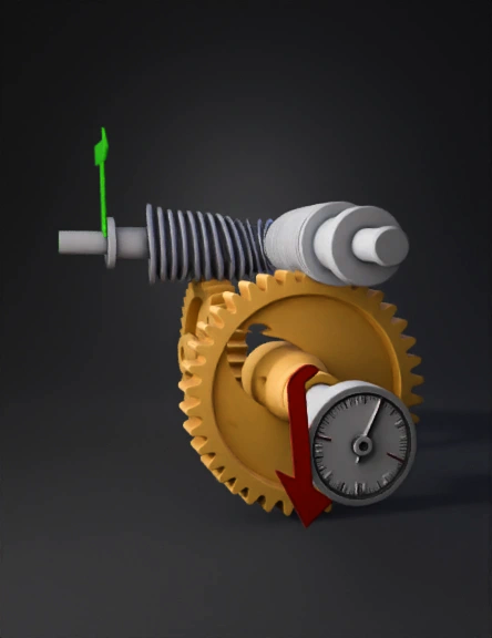
two-stage worm gear 3d model
Tags
machine
rendering
realistic
Prompt
Draw a two-stage worm gear system connected in series: FIRST WORM GEAR (left side): - Draw a horizontal silver threaded rod (Worm 1) - Below it, draw a gold gear wheel with 20 teeth (Wheel 1) - Worm 1 meshes with Wheel 1 - ratio 20:1 THE CONNECTION (CRITICAL): - The OUTPUT SHAFT of the first worm gear (coming from Wheel 1's center) - is DIRECTLY MOUNTED TO the INPUT SHAFT of the second worm gear - This means: the axle coming out of Wheel 1 becomes the axle for Worm 2 SECOND WORM GEAR (right side): - On this same axle, mount another horizontal silver threaded rod (Worm 2) - Below Worm 2, draw a gold gear wheel with 18 teeth (Wheel 2) - Worm 2 meshes with Wheel 2 - ratio 18:1 PATH OF POWER: - Turn Worm 1 → Wheel 1 rotates → its output shaft rotates → Worm 2 rotates (because mounted on same shaft) → Wheel 2 rotates LABELS: - "20:1" near first pair - "18:1" near second pair - "360:1" at bottom - Green arrow pointing INTO Worm 1 (input) - Red arrow pointing OUT OF Wheel 2 with dial (ou
Detailed Info
Related Models
Enter invite code
Enter invite code to get credits!