3D Workspace
Home
Assets
Affiliate Program
Creator Program
Sign up/Log in
View Plans
DCC Bridge
aathithyankiruba
02-05 17:15
Model Name
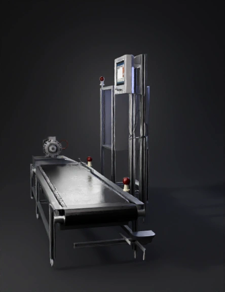
industrial conveyor 3d model
Tags
conveyor
conveyor belt system
industrial conveyor
machine
machine realistic
machine simulation
machine simulation realistic
realistic
simulation
simulation realistic
Prompt
enerate a high-precision industrial CAD assembly of an automated conveyor weighing and detection system. Do NOT include factory environment, floor, humans, or background scene. Show only the conveyor assembly, control panel, sensors, and electrical components. SYSTEM OVERVIEW A belt conveyor integrated with 4-corner load cell weighing system, Siemens S7-200 PLC control, KTP700 HMI display, through-beam object detection sensors, LED status indicator, and 24V DC SMPS power supply. MECHANICAL ASSEMBLY Conveyor System: Industrial belt conveyor with metal frame Drive motor with gearbox mounted on one side Roller set (drive roller + idler roller) Mounting plates for load cells under frame WEIGHING SYSTEM Load Cells: 4 × Single Point Load Cells Mounted at 4 corners under conveyor platform Each load cell bolted to base plate and conveyor plate Load Cell Wiring: 4 load cells wired to junction box or weight transmitter Shielded signal cable routing CONTROL PANEL COMPONENTS Power Supply: 24V DC Industrial SMPS DIN rail mounted Controller: Siemens SIMATIC S7-200 PLC DIN rail mounted Terminal blocks for field wiring HMI: Siemens KTP700 Basic HMI Panel door mounted Display shows real-time weight value SENSOR SYSTEM Through Beam Sensor Pair Mounted on Conveyor Frame: LS35CI.XR1/XX-M12 → Transmitter LE35CI.XR1/LG-200-M12 → Receiver Sensors facing each other across belt path M12 connector cables INDICATOR SYSTEM Industrial LED indicator lamp ON when weight measurement active or object detected ELECTRICAL DETAILS Show cable routing only inside system Separate power and signal wiring paths Show M12 connectors for sensors Show load cell signal cable shielding PART NOTATION REQUIREMENTS Add engineering callouts and labels for each component: Example Format: P1 – 24V DC SMPS PLC1 – Siemens S7-200 PLC HMI1 – Siemens KTP700 LC1, LC2, LC3, LC4 – Load Cells TX1 – LS35CI Transmitter RX1 – LE35CI Receiver LED1 – Status Indicator JB1 – Load Cell Junction Box VIEW REQUIREMENTS Generate: Full Assembly View Control Panel Internal Layout View Bottom View Showing Load Cell Mounting Sensor Alignment Side View STYLE Engineering CAD reference model Clean neutral background only Accurate industrial proportions No artistic styling No environment or factory scene DETAIL LEVEL Bolt level mounting detail Connector level detail DIN rail mounting detail Terminal wiring detail Output as mechanical + electrical reference assembly.
Detailed Info
Related Models
Enter invite code
Enter invite code to get credits!