3D Workspace
Home
Assets
Affiliate Program
Creator Program
Sign up/Log in
View Plans
DCC Bridge
smmkaxoapdjjjxjkaskks
11-17 22:35
Model Name
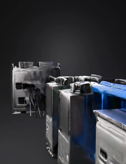
industrial energy system 3d model
Tags
biogas
machine
machine realistic
machine simulation
machine simulation realistic
realistic
simulation
simulation realistic
Prompt
Generate a complete industrial 3D energy system composed of separate assets. Every asset must be exported as an independent GLB mesh with clean geometry and hard-surface industrial design. Maintain logical electrical and gas flow alignment. Do not simplify, replace or reorganize the sequence. Do not remove any device. Follow the exact order below. MANDATORY SPACING RULE: All assets MUST remain clearly separated with a minimum spacing of 0.5–1.0 meters between units. Do NOT fuse, merge, overlap, or visually combine any equipment. SHAPE RULE: – ONLY the Biogas Storage Tank may be cylindrical. – ALL other assets MUST be rectangular, flat-panel industrial enclosures. – The Gas Purification Unit MUST be generated and may NOT be omitted. --------------------------------------------------------- ASSET 1 — BIOGAS STORAGE UNIT (LARGE CYLINDRICAL TANK) --------------------------------------------------------- Large cylindrical industrial biogas tank. Approx dimensions: 3.5 m diameter × 4.0 m height. Painted industrial green. Include: pressure relief valve, safety valve, liquid level gauge, top access hatch. Add RAW GAS outlet flange (Ø0.25 m) on the right side. One green RAW GAS pipeline MUST go ONLY to the purification unit. This asset is required and cannot be skipped. --------------------------------------------------------- ASSET 2 — GAS PURIFICATION UNIT (MANDATORY) --------------------------------------------------------- Rectangular purification module. Dimensions: 2.7 × 2.0 × 2.6 m. MUST always be generated. Features: RAW GAS inlet (Ø0.25 m) on the left, connecting ONLY from the tank. Three CLEAN GAS outlets (each Ø0.20 m) on the right. Blue pipelines MUST go to each SOFC module. Include filters, indicator lights, service doors, bolts, structural frame. --------------------------------------------------------- ASSET 3 — PIPELINES FOR GAS TRANSPORT --------------------------------------------------------- Green pipeline: Tank → Purifier Blue pipelines: Purifier → 3 SOFC modules Must include elbow joints, flanges, industrial thickness, proper routing. NO gas pipeline may connect to electrical devices. --------------------------------------------------------- ASSET 4 — SOFC MODULES (EXACTLY 3 UNITS, NO EXCEPTIONS) --------------------------------------------------------- Generate THREE independent SOFC modules (SOFC_01, SOFC_02, SOFC_03). Dimensions per module: 2.4 × 1.3 × 2.0 m. Rectangular brushed-steel enclosure, vents, removable top cover, bolted base. GAS: – CLEAN GAS INLET on LEFT side (Ø0.20 m). Connect ONLY to blue pipelines from the purifier. – REAR EXHAUST OUTLET (Ø0.20 m). Exhaust MUST NOT appear on top or sides. ELECTRICAL: – SOFC outputs ONLY DC electricity. – Two TOP DC BUSBARS (copper rails, 0.5 m long) mounted on ceramic insulators. – One DC disconnect switch on top. – One grounding bar on the side. SOFC CLEAN TOP RULE (MANDATORY): The TOP of every SOFC MUST be flat and clean. NO pipes, tubes, cylinders, ducts, exhausts, fans, vents, chimneys, wires, hoses, or extra structures may appear on top. ONLY the DC busbars, their ceramic insulators, and one DC disconnect switch are allowed. PLACEMENT: The 3 SOFC modules MUST be placed in a row between the purifier and the DC combiner with 0.5–1.0 m spacing. They must NOT merge, touch, or form a single block. --------------------------------------------------------- ASSET 5 — DC COMBINER PANEL --------------------------------------------------------- Rectangular black cabinet. Dimensions: 1.0 × 0.8 × 1.8 m. Inputs: DC from the 3 SOFC modules ONLY. Output: consolidated DC bus. Include meters, fuses, and cable trays. Must NOT receive AC or gas connections. --------------------------------------------------------- ASSET 6 — DC–AC INVERTER --------------------------------------------------------- Rectangular orange/grey cabinet. Dimensions: 1.0 × 0.8 × 1.9 m. Input: DC from combiner. Output: three-phase AC 220/440 V. Include fans, vents, terminal block. Must be placed AFTER the combiner and BEFORE the UPS. --------------------------------------------------------- ASSET 7 — UPS ENERGY STORAGE CABINET --------------------------------------------------------- Rectangular dark grey UPS. Dimensions: 1.1 × 0.9 × 1.9 m. Input: AC from inverter. Output: conditioned AC to Data Center. Include battery modules and monitoring screen. Must be placed after the inverter with the required spacing. --------------------------------------------------------- ASSET 8 — DATA CENTER --------------------------------------------------------- Rectangular industrial module. Dimensions: 4.5 × 3.0 × 3.0 m. Input: AC from UPS. Include HVAC rooftop units, metallic wall panels, cable entry ports, grounding system. Represents main AC load. --------------------------------------------------------- ASSET 9 — NATIONAL GRID INTERFACE --------------------------------------------------------- Rectangular utility cabinet. Dimensions: 1.6 × 1.0 × 2.0 m. Input: AC from Data Center. Include breaker section, CT/PT metering, utility disconnect, grounding electrode. MUST be final asset connected to the national electrical grid. --------------------------------------------------------- MANDATORY SYSTEM SEQUENCE --------------------------------------------------------- 1. Cylindrical Biogas Tank → 2. Gas Purification Unit → 3. Three SOFC Modules → 4. DC Combiner → 5. DC–AC Inverter → 6. UPS → 7. Data Center → 8. National Grid Interface. --------------------------------------------------------- MANDATORY FLOW RULES --------------------------------------------------------- GAS FLOW (strict): Tank → Purifier → 3 SOFC modules (CLEAN GAS) SOFC → Only rear exhaust NO gas pipe may attach to electrical equipment. ELECTRICAL FLOW (strict): SOFC (DC) → DC Combiner → DC–AC Inverter → UPS → Data Center → National Grid NO AC may enter SOFC modules. NO DC bypasses the inverter. --------------------------------------------------------- FINAL REQUIREMENTS --------------------------------------------------------- Assets MUST NOT merge or overlap. Only the tank may be cylindrical; all other equipment MUST be rectangular. Top of SOFC must be clean with no extra tubes. Deliver separate, clean GLB meshes ready for assembly.
Detailed Info
Related Models
Enter invite code
Enter invite code to get credits!