3D Workspace
Home
Assets
Affiliate Program
Creator Program
Sign up/Log in
View Plans
DCC Bridge
castanedamauricio426
11-17 21:56
Model Name
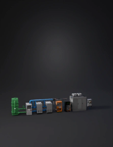
industrial energy system 3d model
Tags
biogas
machine
machine realistic
machine rendering
machine rendering realistic
realistic
rendering
rendering realistic
Prompt
Generate a complete industrial 3D energy system composed of separate assets. Every asset must be exported as an independent GLB mesh with clean geometry and hard-surface industrial design. Maintain logical electrical and gas flow alignment. Do not simplify, replace or reorganize the sequence. Do not remove any device. Follow the exact order below. ASSET 1 — BIOGAS STORAGE UNIT Large rectangular biogas supply tank. Dimensions: 3.0 × 2.5 × 2.8 m. Painted industrial green. Include raw-gas outlet flange (Ø0.25 m) on the right side. Add pressure regulator, safety valve, and two top inspection hatches. One pipeline must exit to the right carrying RAW GAS to the purification stage. ASSET 2 — GAS PURIFICATION UNIT Rectangular purification module. Dimensions: 2.7 × 2.0 × 2.6 m. Include RAW GAS inlet flange (Ø0.25 m) on the left connected from the biogas tank. Add CLEAN GAS outlet flanges (three outputs, each Ø0.20 m) on the right side. Painted light grey. Add filters, indicators, service door, and structural frame. Blue pipelines must exit toward SOFC modules. ASSET 3 — PIPELINES FOR GAS TRANSPORT Green pipeline for RAW GAS (tank → purifier). Blue pipelines for CLEAN GAS (purifier → three SOFC modules). Each pipeline must include elbows, flanges, realistic thickness, and industrial routing. Do not modify colors. ASSET 4 — SOFC MODULES (MANDATORY: EXACTLY 3 UNITS) Keep all original instructions and add the following: Generate THREE independent SOFC modules instead of one. Each module must be exported as a separate GLB mesh (SOFC_01, SOFC_02, SOFC_03). Dimensions per module: 2.4 × 1.3 × 2.0 m. Design: brushed-steel rectangular enclosure, vents, top removable cover, bolted base. Gas: CLEAN-GAS INLET on the LEFT side (Ø0.20 m) for each module, connected directly to the three clean-gas blue pipelines from the purifier. Rear EXHAUST OUTLET (Ø0.20 m). Electrical: TOP DC BUSBARS (positive and negative copper rails 0.5 m long), DC disconnect switch, and grounding bar. Placement: all three SOFC modules MUST be placed in a row directly AFTER the gas purification unit and BEFORE the DC combiner panel. Preserve original placement logic and do not move any other device. ASSET 5 — DC COMBINER PANEL Rectangular black cabinet. Dimensions: 1.0 × 0.8 × 1.8 m. Inputs: DC from the three SOFC modules ONLY. Outputs: single consolidated DC bus (positive and negative rails). Include meters, fuse holders, and top cable trays. ASSET 6 — INVERTER DC–AC Rectangular orange or grey industrial cabinet. Dimensions: 1.0 × 0.8 × 1.9 m. Input: DC from the DC combiner. Output: three-phase AC (220/440 V). Include fans, vents, electrical nameplate, terminal block area. The inverter MUST be placed after the DC combiner and BEFORE the UPS. DO NOT place it anywhere else or connect it directly to the SOFC modules. ASSET 7 — UPS ENERGY STORAGE CABINET Dark grey or black UPS cabinet. Dimensions: 1.1 × 0.9 × 1.9 m. Input: AC from the inverter. Output: conditioned AC to the Data Center. Include battery module slots, vents, and monitoring screen. Place it directly after the inverter. Do not reposition other devices. ASSET 8 — DATA CENTER / MAIN LOAD Large rectangular data center module. Dimensions: 4.5 × 3.0 × 3.0 m. Input: AC from UPS. Features: HVAC rooftop units, server racks internally (not necessary to show inside geometry), metallic paneling, cable entry ports, grounding bar. This represents the final AC load and must remain at the end of the electrical chain before the grid. ASSET 9 — GRID INTERFACE / NATIONAL ELECTRICAL GRID CONNECTION Rectangular utility interconnection cabinet. Dimensions: 1.6 × 1.0 × 2.0 m. Input: AC from the Data Center output. Include: main breaker section, metering zone (CT/PT), utility disconnect switch, grounding electrode. This cabinet represents the final connection to the NATIONAL ELECTRICAL GRID. It MUST be placed at the far right end, AFTER the data center. It may not appear earlier in the chain. SYSTEM SEQUENCE (MANDATORY, DO NOT CHANGE): 1. Biogas Tank → 2. Gas Purification → 3. Three SOFC Modules → 4. DC Combiner → 5. DC–AC Inverter → 6. UPS → 7. Data Center → 8. National Grid Interface. All assets must align in this exact order and respect the flow direction: Gas uses pipes, electricity uses conduits or trays. Do not use spherical shapes. Keep everything rectangular and industrial. Final output: separate, clean GLB meshes ready for assembly.
Detailed Info
Related Models
Enter invite code
Enter invite code to get credits!