3D Workspace
Home
Assets
Affiliate Program
Creator Program
Sign up/Log in
View Plans
DCC Bridge
castanedamauricio426
11-17 20:50
Model Name
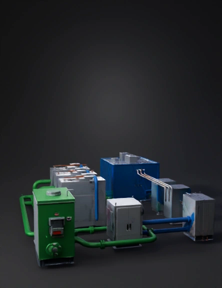
industrial power system 3d model
Tags
biogas
machine
machine realistic
machine rendering
machine rendering realistic
realistic
rendering
rendering realistic
Prompt
Generate a precise industrial 3D model of a biogas-to-electricity SOFC power system with real-world dimensions in meters. Use hard-surface CAD geometry only. No cylindrical tanks or spherical vessels. 1. Biogas storage unit: Rectangular geometry: 4.0 m length × 2.2 m width × 2.5 m height. Painted industrial green. Include pressure regulation manifold, emergency shutoff valve, grounding lug, and one raw-gas outlet flange (Ø 0.25 m). 2. Gas purification unit: Place it 1.2 m to the right of the storage unit. Dimensions: 3.2 m × 2.0 m × 2.4 m. Gray steel enclosure with front access doors, panel hinges, media filter housing, sensor ports, and inlet/outlet flanges (Ø 0.25 m). 3. Gas pipelines: Raw biogas line (green): Ø 0.25 m, running 1.0 m above ground from storage outlet to purifier inlet. Use straight sections, flange joints, and 90-degree elbows (radius 0.35 m). Clean gas lines (blue): Ø 0.20 m, three separate outputs from purifier to each SOFC module. Each line runs 0.8 m above ground and enters each module via aligned flanged ports. 4. SOFC modules: Place three modules in a row, each separated by 1.5 m of clearance. Each SOFC module must be a rectangular stack system with dimensions: 2.4 m length × 1.3 m width × 2.0 m height. Include top service cover, side thermal panels, rear ventilation grills, bolted base frame (0.25 m height), two flanged gas ports (Ø 0.20 m), and electrical DC output zone on top. Add two DC busbars (+ and –) per module: length 0.50 m, copper texture, mounted on insulators. Add a grounding bar on the side. 5. DC electrical system: Create rigid metallic conduits (Ø 0.06 m) carrying DC power from each module to a central DC combiner cabinet. DC combiner cabinet dimensions: 1.6 m × 0.8 m × 2.0 m. Three incoming DC feeds and one outgoing feed to the inverter. Include grounding rods (0.8 m) and cable trays (0.4 m width). 6. Inverter system: Place the inverter 2.0 m to the right of the SOFC line. Cabinet size: 2.2 m × 1.4 m × 2.2 m. Include DC input terminals, AC output terminals, cooling louvers, control interface, cable glands, and external grounding point. 7. UPS / BESS system: Place next to the inverter with a 0.6 m separation gap. Dimensions: 2.2 m × 1.4 m × 2.2 m. Include ventilation frames, battery module panels, DC coupling ports, and grounding lugs. 8. AC power routing: From the inverter, create rigid metallic conduits (Ø 0.08 m) carrying AC output toward the data center. Use support brackets every 1.0 m. Clearly separate AC conduits from gas pipelines. 9. Data center building: Place 4.0 m to the right of the inverter/UPS area. Dimensions: 12 m length × 7 m width × 6 m height. Blue metallic panels, HVAC units, cable intake port, and main electrical distribution access. Overall: Maintain consistent scale, flat industrial ground plane, watertight CAD geometry, sharp edges, metallic PBR textures, and correct separation between gas and electrical systems. Export as GLB with separate meshes for each subsystem.
Detailed Info
Related Models
Enter invite code
Enter invite code to get credits!