3D Workspace
Home
Assets
Affiliate Program
Creator Program
Sign up/Log in
View Plans
DCC Bridge
castanedamauricio426
11-17 21:29
Model Name
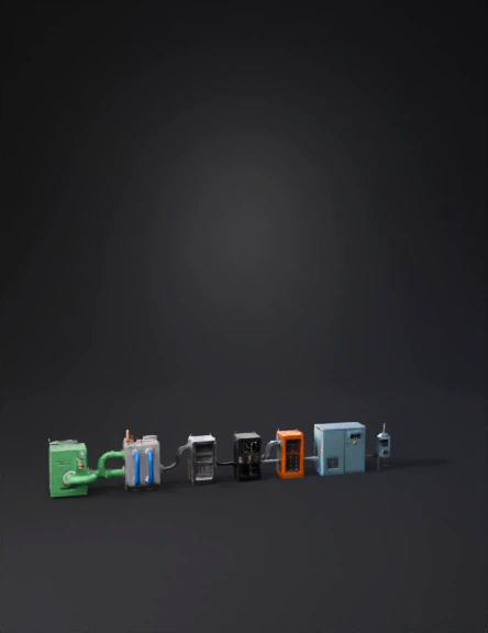
biogas plant 3d model
Tags
biogas
machine
machine realistic
machine rendering
machine rendering realistic
realistic
rendering
rendering realistic
Prompt
Generate CAD-accurate industrial 3D assets for a biogas-to-electricity SOFC plant. All assets must be created as separate meshes (GLB), real scale in meters, hard-surface CAD geometry, and PBR metallic materials. The IA must follow this EXACT technical sequence: RAW GAS → PURIFICATION → SOFC → DC COMBINER → DC/AC INVERTER → UPS → DATA CENTER → NATIONAL GRID. Every asset must include the exact connection points described so the system cannot be assembled incorrectly. ----------------------------------------------------- ASSET 1 — RAW BIOGAS STORAGE (START OF SYSTEM) ----------------------------------------------------- Rectangular storage block: 4.0 × 2.2 × 2.5 m, industrial green steel. Features: – Pressure regulator. – Safety shutoff valve. – Grounding lug. – ONE RAW-GAS OUTLET FLANGE on the RIGHT SIDE, centered at 1.0 m height (Ø 0.25 m). This outlet MUST connect directly to the purification unit inlet. No other asset connects here. ----------------------------------------------------- ASSET 2 — GAS PURIFICATION / DESULFURIZATION MODULE ----------------------------------------------------- Rectangular unit: 3.2 × 2.0 × 2.4 m, gray steel. Connection Points: – RAW-GAS INLET FLANGE on the LEFT side (Ø 0.25 m). Must match Asset 1 outlet. – CLEAN-GAS OUTLET MANIFOLD on the RIGHT side with THREE ports (Ø 0.20 m each). Purpose: Receives raw biogas and outputs clean gas exclusively to the SOFC modules. ----------------------------------------------------- ASSET 3 — GAS PIPELINES (RAW AND CLEAN) ----------------------------------------------------- Create two families: 1) RAW GAS PIPE: Green, Ø 0.25 m. Straight segments + elbows (0.35 m radius). Connects ONLY Storage → Purifier. 2) CLEAN GAS PIPES: Blue, Ø 0.20 m. THREE separate lines. Connect ONLY Purifier → SOFC modules. Must include flanges, supports, clamps, correct alignment. ----------------------------------------------------- ASSET 4 — SOFC MODULE (THIS BLOCK PRODUCES DC) ----------------------------------------------------- Rectangular module: 2.4 × 1.3 × 2.0 m, brushed steel. Connections: – CLEAN-GAS INLET on LEFT side (Ø 0.20 m). Must match Asset 3 blue pipes. – EXHAUST OUTLET on REAR (Ø 0.20 m). Electrical outputs: – TOP DC BUSBARS: two copper rails (+ and –), 0.5 m long, on insulated supports. – DC DISCONNECT SWITCH beside busbars. – GROUNDING BAR on side. Purpose: This asset outputs **DC POWER**. Not AC. Must connect ONLY to the DC Combiner. ----------------------------------------------------- ASSET 5 — DC COMBINER CABINET (MANDATORY BEFORE INVERTER) ----------------------------------------------------- Dimensions: 1.6 × 0.8 × 2.0 m, gray. Connections: – THREE DC INPUT TERMINALS on LEFT side (one from each SOFC). These MUST physically match the SOFC DC outputs. – ONE DC OUTPUT TERMINAL on RIGHT side (goes to inverter). Internal: – DC busbars, fuses, protection system, grounding rod. Purpose: This cabinet consolidates all SOFC DC outputs. The inverter MUST NOT be connected directly to SOFC modules — only through this cabinet. ----------------------------------------------------- ASSET 6 — DC-TO-AC INVERTER (PLACED DIRECTLY AFTER COMBINER) ----------------------------------------------------- Cabinet: 2.2 × 1.4 × 2.2 m, dark gray. Connections: – ONE DC INPUT TERMINAL on LEFT side (must match the combiner DC output). – AC OUTPUT TERMINALS on RIGHT side. – Cooling grills, cable glands, and grounding point. Purpose: Converts the combined SOFC DC into three-phase AC. This inverter MUST NOT be placed anywhere else. It MUST be after the combiner. ----------------------------------------------------- ASSET 7 — UPS / BATTERY STORAGE (MUST CONNECT AFTER THE INVERTER) ----------------------------------------------------- Cabinet: 2.2 × 1.4 × 2.2 m, orange. Connections: – AC INPUT TERMINAL on LEFT side (must match inverter AC output). – AC OUTPUT TERMINAL on RIGHT side (goes to Data Center). Features: – Battery modules, internal BESS, cooling intakes, grounding. Purpose: Stabilizes the AC supply. This unit must be placed strictly between the inverter and the Data Center. ----------------------------------------------------- ASSET 8 — AC POWER CONDUITS (UPSTREAM AND GRID FEED) ----------------------------------------------------- Conduits: Metallic, Ø 0.08 m. Create: – AC conduits from INVERTER → UPS. – AC conduits from UPS → DATA CENTER. – AC GRID FEED LINE: From UPS AC output → NATIONAL GRID CABINET. Each conduit must connect only to the correct terminal. ----------------------------------------------------- ASSET 9 — DATA CENTER BLOCK (FINAL LOAD) ----------------------------------------------------- Metallic light-blue building: 12 × 7 × 6 m. Connections: – AC INTAKE PANEL on LEFT side (must match UPS AC output conduits). Features: – HVAC units, cable entry, grounding point. Purpose: Receives AC from UPS and consumes it as the final load. ----------------------------------------------------- ASSET 10 — NATIONAL ELECTRIC GRID INTERCONNECTION POINT ----------------------------------------------------- Small utility service cabinet or pole-mounted module: 1.2 × 1.2 × 2.0 m. Connections: – AC INPUT from UPS (parallel feed). – Isolation switch. – Utility meter box. – Surge protection. – OUTPUT FEED to the national grid. Purpose: This is the final connection to the National Electrical Grid. Must not connect to SOFC or inverter directly — only through UPS AC output. ----------------------------------------------------- MANDATORY CONNECTION SEQUENCE FOR THE AI: ----------------------------------------------------- RAW GAS: Storage → Purifier CLEAN GAS: Purifier → SOFC modules DC POWER: SOFC modules → DC Combiner DC BUS: DC Combiner → Inverter AC POWER: Inverter → UPS → Data Center GRID FEED: UPS → National Grid Interconnect NO ASSET MAY CONNECT OUTSIDE THIS SEQUENCE. NO INVERTER MAY CONNECT DIRECTLY TO SOFC. NO UPS MAY CONNECT BEFORE THE INVERTER. NO GRID CONNECTION MAY BYPASS THE UPS.
Detailed Info
Related Models
Enter invite code
Enter invite code to get credits!