3D Workspace
Home
Assets
Affiliate Program
Creator Program
Sign up/Log in
View Plans
DCC Bridge
castanedamauricio426
11-17 21:12
Model Name
industrial machinery 3d model
Tags
biogas
industrial machinery
machine
machine realistic
machine simulation
machine simulation realistic
realistic
simulation
simulation realistic
Prompt
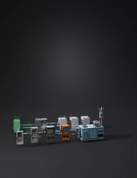
Generate CAD-accurate industrial 3D assets representing a complete biogas-to-electrical-power system. Each subsystem must be modeled as a separate GLB asset with real-scale dimensions in meters, clean hard-surface engineering geometry, PBR metallic materials and watertight topology. All connection points must physically align between assets. Follow the functional sequence: ASSET 1 — RAW BIOGAS STORAGE UNIT Rectangular storage block: 4.0 × 2.2 × 2.5 m, industrial green. Include: pressure regulation manifold, emergency shutoff valve, grounding lug, inspection hatch, and ONE RAW-GAS OUTLET FLANGE on the right side positioned at 1.0 m height (diameter 0.25 m). This flange is the starting point of the process. ASSET 2 — GAS PURIFICATION / DESULFURIZATION MODULE Rectangular steel housing: 3.2 × 2.0 × 2.4 m, matte gray. Include: – RAW-GAS INLET FLANGE (Ø 0.25 m) on the left side, aligned to Asset 1 outlet. – CLEAN-GAS OUTLET MANIFOLD with THREE ports (Ø 0.20 m each) on the right side. – Access doors, catalytic cartridge section, sensor ports, pressure monitoring panel. This asset must receive raw gas and deliver three clean-gas feeds. ASSET 3 — GAS PIPELINE SET Create all gas pipes as separate modular assets: 1) RAW BIOGAS PIPE (green) Ø 0.25 m, straight sections and elbows (radius 0.35 m). Must connect Storage OUTLET to Purifier INLET. 2) CLEAN GAS PIPELINES (blue) Ø 0.20 m, THREE independent lines from Purifier OUTLET ports to the SOFC modules. Include flanges, welded joints, supports, clamps and correct vertical/horizontal alignment. Pipes must connect without distortion. ASSET 4 — SOFC MODULE (x1 unit, to be duplicated three times) Rectangular fuel-cell block: 2.4 × 1.3 × 2.0 m. Brushed stainless steel. Include: – CLEAN-GAS INLET FLANGE Ø 0.20 m on the left side (align to blue pipes). – EXHAUST OUTLET on the rear (Ø 0.20 m). – TOP DC OUTPUT ZONE with TWO DC BUSBARS (positive / negative), 0.5 m long copper rails mounted on ceramic insulators. – DC DISCONNECT SWITCH near the busbars. – Side grounding bar. – Bolted base frame. Each SOFC must output DC power only. ASSET 5 — DC COMBINER / DISTRIBUTION CABINET Gray steel cabinet: 1.6 × 0.8 × 2.0 m. Include: – THREE DC INPUT TERMINALS on the left (one per SOFC module). – INTERNAL BUSBAR BLOCK and fuse holders. – ONE DC OUTPUT TERMINAL on the right for the inverter. – Grounding rod and cable tray entry at the top. This asset must consolidate all SOFC outputs into one DC feed. ASSET 6 — DC–AC INVERTER CABINET Dark gray cabinet: 2.2 × 1.4 × 2.2 m. Include: – DC INPUT TERMINAL on the left (aligning to Combiner output). – THREE-PHASE AC OUTPUT TERMINALS on the right. – Cooling louvers, power electronics block, cable glands, earthing point. This asset converts the DC into AC suitable for the data center. ASSET 7 — UPS / BESS (Battery Energy Storage System) Orange cabinet: 2.2 × 1.4 × 2.2 m. Include: battery module grid, DC coupling port, protection panel, ventilation frames and grounding points. This unit provides backup and transient stability for the inverter output. Place it logically next to the inverter. ASSET 8 — AC POWER CONDUITS AND NATIONAL GRID FEED Create metallic conduits Ø 0.08 m carrying AC output from the inverter to: 1) The DATA CENTER INPUT PANEL. 2) A NATIONAL GRID INTERCONNECTION POINT (a small service cabinet or pole-mount module). The grid connection must include: – AC isolation switch – Utility meter housing – Surge protection device – Feeder conduit to the grid node This ensures safe parallel connection without backfeeding. ASSET 9 — DATA CENTER LOAD BLOCK Rectangular light-blue metallic building: 12 × 7 × 6 m. Include: – MAIN AC INTAKE PANEL on the left side (must connect to inverter AC conduits). – HVAC units, cable entry frame, internal distribution feed. This is the final AC load. CONNECTION SEQUENCE (MANDATORY): 1. RAW GAS flows: Storage → Purifier. 2. CLEAN GAS flows: Purifier → SOFC Modules (x3). 3. SOFC DC POWER flows: Each SOFC → DC Combiner (inputs 1, 2, 3). 4. COMBINED DC POWER flows: DC Combiner → Inverter DC input. 5. AC POWER flows: Inverter AC output → Data Center intake panel. 6. FINAL AC GRID CONNECTION: Inverter AC output → National Grid interconnect cabinet → Utility network. GENERAL REQUIREMENTS: – All assets must remain separate GLB meshes. – All flanges must align physically. – All electrical conduits and busbars must align with terminals. – Use real-scale dimensions in meters. – Clean CAD-like geometry, PBR metal surfaces, sharp edges. – No organic shapes, no merged meshes, no floating geometry.
Detailed Info
Related Models
Enter invite code
Enter invite code to get credits!