3D Workspace
Home
Assets
Affiliate Program
Creator Program
Sign up/Log in
View Plans
DCC Bridge
castanedamauricio426
11-17 21:02
Model Name
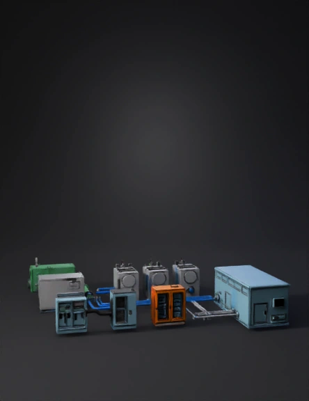
industrial power system 3d model
Tags
biogas
machine
machine realistic
machine simulation
machine simulation realistic
realistic
simulation
simulation realistic
Prompt
Generate separate CAD-style industrial 3D assets for a complete SOFC biogas power system. Use real-scale dimensions in meters, watertight meshes, PBR metallic materials and clean hard-surface geometry. No cylindrical tanks. ASSET 1 — Biogas Storage Unit Rectangular tank: 4.0 × 2.2 × 2.5 m. Industrial green paint. Include: pressure regulation manifold, safety valve, grounding lug and one RAW-GAS OUTLET FLANGE on the right side at 1.0 m height (diameter 0.25 m). This flange must logically connect to the purifier inlet pipe. ASSET 2 — Gas Purification / Desulfurization Unit Rectangular box: 3.2 × 2.0 × 2.4 m. Matte gray steel. Include: – RAW-GAS INLET FLANGE on the left side (Ø0.25 m). – CLEAN-GAS OUTLET MANIFOLD on the right side (three ports, Ø0.20 m each), spaced vertically or horizontally. – Access doors, sensor ports, and a front instrumentation panel. This asset must accept gas from Storage Unit and distribute clean gas to the SOFC modules. ASSET 3 — Raw and Clean Gas Piping Set Produce two pipe families: 1) RAW BIOGAS PIPE (green) Ø0.25 m: straight segments, elbows (radius 0.35 m) and flanges that match the Storage OUTLET and the Purifier INLET. 2) CLEAN GAS PIPES (blue) Ø0.20 m: three independent lines with elbows, flanges and supports. Pipes must connect the Purifier CLEAN-GAS MANIFOLD to each SOFC module INPUT PORT. Meshes should be separate and named logically. ASSET 4 — SOFC Module (x1, to be duplicated) Rectangular module: 2.4 × 1.3 × 2.0 m. Brushed steel. Include: – CLEAN-GAS INLET FLANGE on the left side (Ø0.20 m). – EXHAUST OUTLET FLANGE on the rear (Ø0.20 m). – Top DC power zone with two isolated DC BUSBARS (positive and negative, 0.5 m long). – Side grounding bar. – Bolted base frame. This module must only receive gas from the CLEAN-GAS PIPE and output DC electricity upward. ASSET 5 — DC Combiner Cabinet Gray cabinet: 1.6 × 0.8 × 2.0 m. Includes: – Three DC INPUT TERMINALS (one from each SOFC) on the left. – One DC OUTPUT TERMINAL to the inverter on the right. – Internal busbar block, fuse holders and grounding rod. – Cable tray or conduit entry on the top. This asset consolidates DC from the SOFC modules. ASSET 6 — Inverter Cabinet (DC → AC) Dark gray cabinet: 2.2 × 1.4 × 2.2 m. Include: – One DC INPUT terminal on the left (must connect to combiner output). – Three-phase AC OUTPUT terminals on the right. – Cooling louvers and cable glands. – Separate grounding point. This unit converts DC into AC for the Data Center. ASSET 7 — UPS / Battery Energy Storage Orange cabinet: 2.2 × 1.4 × 2.2 m, placed logically next to the inverter. Include: battery module grids, DC coupling terminals, ventilation panels, grounding lugs. This asset stabilizes the inverter. ASSET 8 — AC Power Conduits Metallic conduits Ø0.08 m, with brackets and supports, that connect the inverter AC OUTPUT to the Data Center INPUT PANEL. Meshes separate for direction, elbows and joints. ASSET 9 — Data Center Load Block Metallic light-blue rectangular building: 12 × 7 × 6 m. Include: – MAIN AC INTAKE PANEL on the left side (must connect to inverter conduits). – HVAC units, cable entry port, grounding point. This is the final AC load. General rules: Maintain logical physical connections between all assets. Gas flows: Storage → Purifier → SOFC. Electrical flows: SOFC (DC) → DC Combiner → Inverter (DC→AC) → Data Center (AC). Do not merge meshes. Do not generate organic shapes. Export all assets as separate GLB models with accurate pivots and clean topology.
Detailed Info
Related Models
Enter invite code
Enter invite code to get credits!