3D Workspace
Home
Assets
Affiliate Program
Sign up/Log in
?
Upgrade
DCC Bridge
Anonymous1773275167
03-12 00:37
Model Name
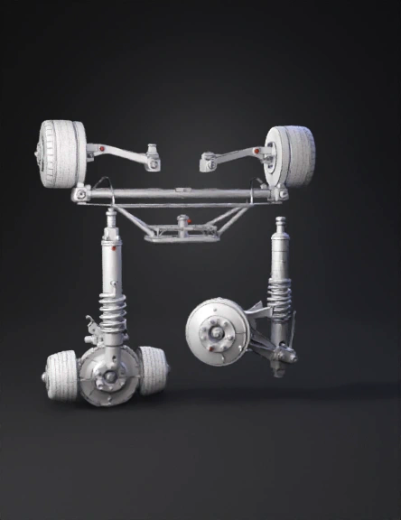
suspension 3d model
Tags
axle
mechanical
realistic
simulation
simulation realistic
vehicle
vehicle realistic
vehicle simulation
vehicle simulation realistic
wishbone
Prompt
Here is the prompt in English: PROMPT: You are an expert mechanical CAD designer. Help me design a 4-corner double wishbone suspension system in SolidWorks based on the chassis and wheel dimensions provided below. Explain step by step how to model each part individually. CHASSIS DIMENSIONS: Total chassis width: 1565mm Total chassis length: 1638mm Main longitudinal rails: center X = ±229mm, 50×50mm square tube profile Outer upright rails: X = ±432mm Rail height: Y = 0 to 50mm (tube top surface at Y=50mm) Front axle Z position: +737mm Rear axle Z position: -737mm WHEEL DIMENSIONS: Outer diameter: 380mm Width: 180mm Wheel center X: ±648mm (from chassis centerline) Wheel center height from ground (Y): 241mm Wheel center Z: front +737mm, rear -737mm PARTS TO BE MODELED WITH DIMENSIONS: LOWER WISHBONE (A-arm) — separate for left and right: Material: 25mm OD, 2mm wall thickness steel tube Front arm length: 245mm Rear arm length: 245mm Distance between two inner pivot points (chassis side): 160mm (±80mm along Z axis) Single outer ball joint point Chassis pivot point: X=±432mm, Y=110mm, Z=±(737mm ± 80mm) Outer ball joint point: X=±648mm, Y=130mm, Z=±737mm Profile: triangular A-shape truss UPPER WISHBONE (A-arm) — separate for left and right: Material: 22mm OD, 2mm wall thickness steel tube Front arm length: 195mm Rear arm length: 195mm Distance between two inner pivot points (chassis side): 120mm (±60mm along Z axis) Chassis pivot point: X=±411mm, Y=341mm, Z=±(737mm ± 60mm) Outer ball joint point: X=±617mm, Y=338mm, Z=±737mm Profile: triangular A-shape truss UPRIGHT (Knuckle): Shape: straight cylindrical vertical link OD: 40mm, wall thickness: 4mm Total height: 210mm Bottom end (lower ball joint): X=±648mm, Y=130mm, Z=±737mm Top end (upper ball joint): X=±617mm, Y=338mm, Z=±737mm Slight angle between two ends (approximately 8 degrees outward from chassis) HUB (Wheel Spindle): OD: 70mm, ID: 40mm Length: 120mm Center point: X=±648mm, Y=241mm, Z=±737mm Mounted perpendicular to upright BRAKE DISC (Rotor): Outer diameter: 320mm Inner diameter (hat channel): 160mm Thickness: 28mm Mounted to outer face of hub COILOVER (Shock Absorber + Spring): Shock body: 60mm diameter, 210mm length Shock rod: 36mm diameter, 170mm length (slides into body) Total length (fully extended): 380mm Coil spring: 100mm diameter, 180mm length, 12mm wire diameter Lower mount point: near midpoint of lower A-arm — X=±540mm, Y=145mm, Z=±737mm Upper mount point: inner chassis rail — X=±298mm, Y=508mm, Z=±737mm Mounting angle: approximately 25 degrees inward toward chassis centerline CHASSIS BRACKETS (per corner): Lower wishbone front bracket: 60×50×5mm flat plate, X=±432mm, Z=±657mm Lower wishbone rear bracket: 60×50×5mm flat plate, X=±432mm, Z=±817mm Upper wishbone front bracket: 50×40×5mm flat plate, X=±411mm, Z=±677mm Upper wishbone rear bracket: 50×40×5mm flat plate, X=±411mm, Z=±797mm Coilover top bracket: 60×30×5mm flat plate, X=±298mm, Y=508mm, Z=±737mm SOLIDWORKS ASSEMBLY RULES: Model each part as a separate .sldprt file first In the assembly, fix the chassis (Fixed mate) Apply Concentric + Coincident Mates to lower A-arm chassis pivot connections Apply Concentric + Coincident Mates to upper A-arm chassis pivot connections Connect upright to upper and lower ball joint points using Point Mates Connect hub to upright using Concentric Mate Apply Concentric Mates to both upper and lower coilover mount points Connect wheel to hub using Concentric + Coincident Mates Leave enough degrees of freedom in all mates so suspension can travel up and down independently After completing one side, use Mirror Components in the Assembly, but select "Create opposite hand version" so each side can be controlled independently EXPECTED RESULT: A fully functional 4-corner double wishbone suspension system. Each wheel must be able to travel up and down independently. The coilover must be able to compress and extend under load. The brake disc and hub assembly must be correctly connected to the wheel. All parts must be physically attached to the chassis outer rails (X=±432mm) and correctly positioned.
Detailed Info
Related Models
Enter invite code
Enter invite code to get credits!