3D Workspace
Home
Assets
Affiliate Program
Creator Program
Sign up/Log in
View Plans
DCC Bridge
rudra.munirai2024
02-27 14:44
Model Name
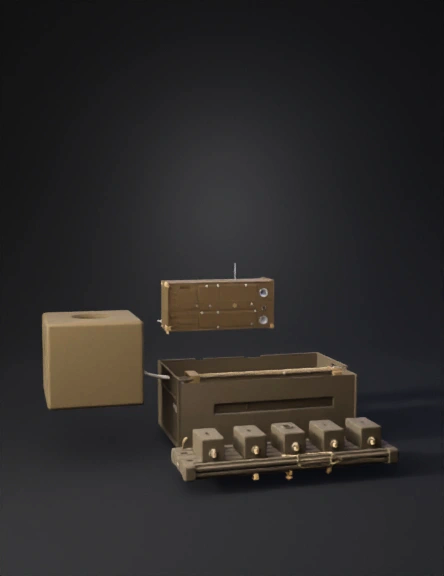
particle accelerator 3d model
Tags
accelerator
beam
machine
machine realistic
machine simulation
machine simulation realistic
realistic
simulation
simulation realistic
Prompt
I. The Global Coordinate SystemZ-Axis (Length): 0m (Beam Exit) to 15m (End of Setup).X-Axis (Horizontal): ± 0.5m from the center of the beam.Y-Axis (Vertical): Beam height is typically 1.2m from the floor.II. Component-by-Component Specifications1. Beam Entrance & Shaping (0m - 3m)Shielding Wall (0m): A 1m thick concrete block with a 10cm circular hole in the center.Dipole Bending Magnet (1.0m): * Volume: Large iron block (~1.5m x 1m x 1m).Geometry: C-shaped or H-shaped frame with copper coils. The beam path curves slightly through its center.Collimators (2.5m): * Volume: Two rectangular Tungsten blocks (each 10cm x 10cm x 5cm).Placement: Placed on motorized rails. They should leave a tiny 2mm x 2mm square gap exactly at the beam center.2. The Trigger Telescope (3m - 12.5m)Scintillator 1 (S1) (4.0m):Active Area: 2cm x 2cm x 0.5cm (Plastic Square).Housing: Attached to a cylindrical Photomultiplier Tube (PMT) (approx. 5cm diameter, 20cm long).Wrapping: Wrapped in black light-tight tape.The Drift Gap (4m - 12m): * Distance: Exactly 8,000 mm. This space must be empty to allow for the 8-meter Time-of-Flight measurement.Scintillator 2 (S2) (12.0m):Specs: Identical to S1 (2cm x 2cm paddle + PMT).Placement: Must be perfectly aligned with S1 on the Z-axis.3. High-Precision Tracking (13.0m - 13.5m)Delay Wire Chambers (DWC 1, 2, 3):Volume: Three square frames (approx. 20cm x 20cm x 5cm).Internal Geometry: Central "window" of 10cm x 10cm where the thin wires are located.Placement: Spaced exactly 25cm apart (at 13.0m, 13.25m, and 13.5m).Importance: These reconstruct the $(x,y)$ entry path with 0.21mm resolution.4. The Interaction Zone (14.0m)Water Phantom (The Target):Volume: A clear acrylic/Plexiglass cube (40cm x 40cm x 40cm).Content: Filled with distilled water.Placement: Center of the front face at 14.0m.Scanning Scintillator (S3):Size: Very small "finger" scintillator (1cm x 1cm).Mechanism: Mounted on a robotic 1D rail inside the water tank.Movement: Moves along the Z-axis from 0cm to 30cm depth inside the water.III. Electrical & Data Connections (The "Nerves")Cables: Every PMT (S1, S2, S3) and DWC must have high-voltage (SHV) and signal (BNC/LEMO) cables running to the DAQ Rack.The DAQ Rack: A standard 19-inch electronics rack (positioned to the side at 15m) containing:HV Power Supply: Where you apply the 1400V–2100V for the Golden Operating Point.Discriminators: Where you set the Signal Threshold ($T$) to block noise.Coincidence Module: The logic gate connecting S1 and S2.IV. Summary of Settings for the ModelBeam Type: Proton-only (visualize as a thin blue laser line).Beam Energy: 1 GeV (Initial) / 150 MeV (Medical Mapping).Critical Distance: The 8m gap is the most important visual element—it represents the ToF "speedometer."The Bragg Peak: The 3D model should show the beam "stopping" and creating a bright glow at 11cm depth inside the water phantom.
Detailed Info
Related Models
Enter invite code
Enter invite code to get credits!